
“You’ll learn how to create an automation system to communicate 3 Arduinos via RS485.
What project will you develop?
The project consists of 3 Arduino’s. We have an Arduino UNO, a Nano, and a MEGA. The Arduino UNO will control the other 2 and send commands to receive the reading of the analog signal from the potentiometer connected to each Arduino.
He will receive the signal and present it on the LCD screen.
This communication will be developed through the use of RS-485 modules. See the circuit below.
The MAX485 can transmit this data over a distance of 1200 m, in addition, it has high immunity to electromagnetic interference. This is one of the reasons why it is widely used by industrial devices, such as programmable logic controllers.
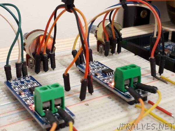
To make this communication we use the Arduino MAX485 module. This module will allow us to interconnect the devices and carry out our communication. See the photo of the module.
The board presents the complete circuit for you to transfer and receive data between the boards. The connecting pins are quite easy for you to learn.
Observe the figure and see that it is formed by 8 pins: DI, DE, RE,R0,VCC, A, B, and GND.
Shall we understand the function of each of them?
Pins DI and R0 are used to transmit data (DI - Data Input) and receive data (RO - Received Output). Connect the TX pin to the DI and the RX to the RO.
The configuration of the data transfer or reception mode is done through the DE and RE pins. The first thing you must do is connect the pins with a jumper.
Then, you must apply 5V to put the circuit in transfer mode and 0V to receive data. See the circuit in the figure and analyze the connection on the DE and RE pins.
In addition to these pins, we have VCC, A, B, and GND. The VCC and GND are used to supply the module circuit, while A and B will be responsible for transmitting information from one module to another with RS-485 voltage levels.
All pins of Letter A must connect to each other. This rule also applies to B.
Now you will learn the programming logic and the complete circuit for this project.”