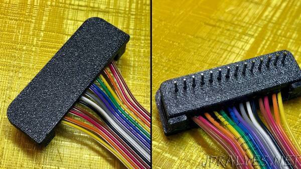
“In order to test the input panel, I had to connect the 14 lines to the test setup on a breadboard. Just using a pin header was too flimsy for me, because I often reuse these test connectors on different breadboards. In this short article, I explain how I made it into a solid connector.”
Related Content
Related Posts:
- 3D Printeed Mars Rover Using ESP12E
- A Linear LED Clock for Your Desktop
- Animatronic Fox Head - Companion Bot
- CH32V003 FM Radio Receiver with RDS
- Cyber Clock an IoT OLED Desk Clock With Hygro-Thermometer
- Electromagnetic Field Meter (EMF meter)
- ESP32 based intruder detection system
- IAQ Monitoring using Digital Art w/ RPI & Processing & Cloud
- LED Tester & Calculator
- Modular Macro Keyboard System — Ocreeb MK2