
“This is something I built from a published schematic late in the 1980s. It works very well. I gave away the magazine with the schematic because I believed I would never need it again and we were downsizing.
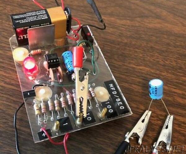
The circuit is built around a 555 timer. These are very inexpensive and very available. I am always nervous about ruining a semiconductor by applying too much heat while soldering, so I used an 8 pin socket and soldered it into place. Then I pressed the 555 timer chip into the socket when the soldering was finished.
The photo shows my tester. I drilled holes through 1/8 inch Plexiglas to make a circuit board. Just decide where each component should be located and mark the location for the holes. Drill with a small drill. I place the component on top of the Plexiglass and connect leads below the Plexiglass. There is a selector for different resistance arrays. I tapped the Plexiglass for 8-32 brass screws. I soldered leads to the screw heads under the Plexiglass and I attach an alligator clip to the appropriate screw for the desired resistance range on each test. I used hot glue to fasten components to the Plexiglass where necessary. The battery holder is fastened to the Plexiglass with a screw.”