
Introduction
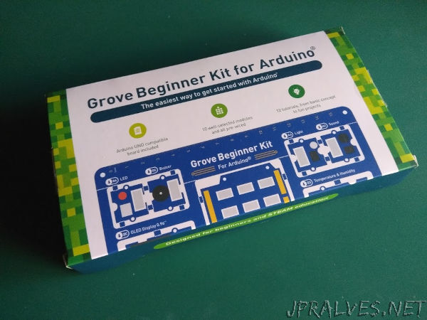
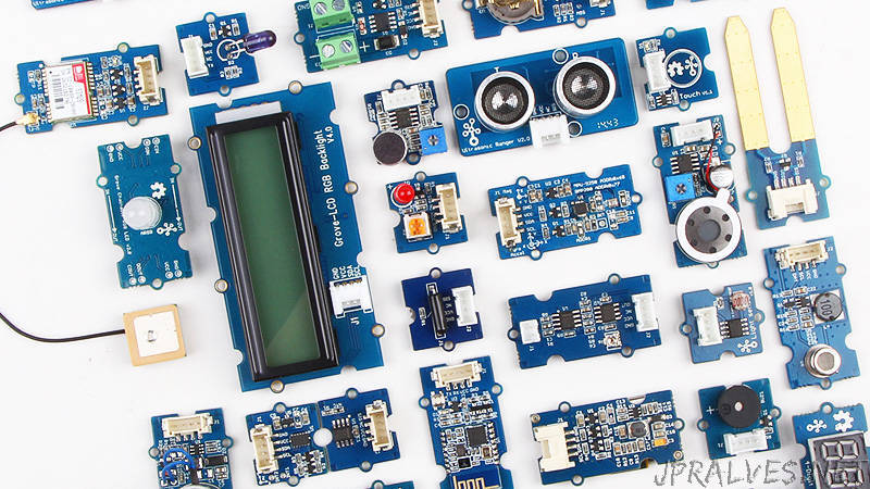
Today I received the Grove Beginner Kit for Arduino from Seeed Studio.
The first impression I had is this Kit is very good! Delivered in a very nicely built box. The experience of opening the Kit is amazing. The box is built around the PCB and is kept its size to the minimum. The outside of the box is full of details about the Kit itself giving an overview of the components available in the all-in-one kit.
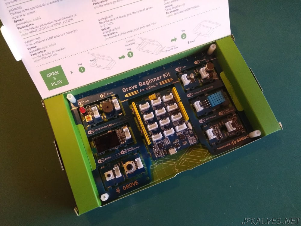
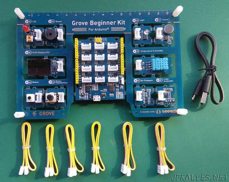
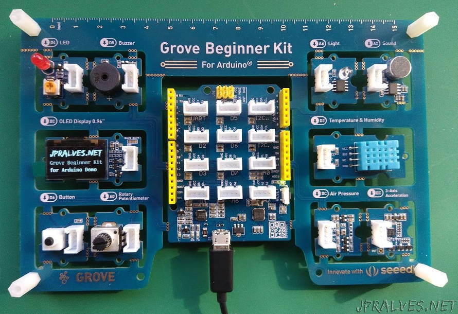
The PCB was designed in a way that it is not necessary to use the Grove cables to connect the modules since the modules are all connected to the Arduino compatible board. It has some snaps that can be used to break the components of the PCB and become individual components. It also features a 15cm ruler, but that is just because.
It also includes 6 Grove cables and a mini USB cable for programming and powering the Arduino board - A Seeeduino Lotus.
About Seeed Studio
Seeed is the IoT hardware enabler providing services over 10 years that empower makers to realize their projects and products. Seeed offers a wide array of hardware platforms and sensor modules ready to be integrated with existing IoT platforms and one-stop PCB manufacturing and Prototype PCB Assembly. Seeed Studio provides a wide selection of electronic parts including Arduino, Raspberry Pi and many different development board platforms. Especially the Grove System help engineers and makers to avoid jumper wires problems. Seeed Studio has developed more than 300 Grove modules covering a wide range of applications that can fulfill a variety of needs.
Kit Features
The Seeeduino Lotus
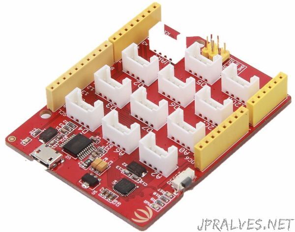
The included Arduino compatible board is a Seeeduino Lotus 1.1. This Board was specifically created for using Grove cables although it is pin compatible with Arduino UNO.
This Board is equipped with an ATmega328P and a CP2102N for USB communications. It is fully compatible with the Arduino UNO and comes with a micro USB port for programming and power.
The board besides the Arduino UNO shield headers it also has 12 Grove Connectors and an ISP Header.
The Grove Connectors are connected to D2-D7, A0, A2 and A6, two connectors for I2C and one for UART (Serial). It has the on-board power and D0, D1 and D13 LEDs and a Reset Button.
For more information about the Seeeduino Lotus please check the page Seeeduino Lotus from Seeed studio Wiki.
The Grove Connector
So, what is a Grove connector?
The grove connector was designed for beginners not have to worry inadvertently damaging the components by connecting then the wrong way. The grove socket only allows the connection in one position. Normal grove cables have 4 pins:
- pin 1 - Yellow - Depends on the module
- pin 2 - White - Depends on the module
- pin 3 - Red - VCC on all Grove Connectors
- pin 4 - Black - GND on all Grove Connectors
When using I2C:
- pin 1 - Yellow - SCL - I2C Clock
- pin 2 - White - SDA - I2C Data
For more information check the page Grove System from Seeed studio Wiki.
There are more than 300 different grove modules available that can be bought separately.
The Modules
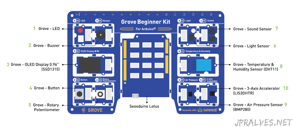
The Kit isn’t complete without describing the modules that come with it.
The modules included in the Kit are:
- 1 - Pin D4 - Grove - Red LED with trimmer
- 2 - Pin D5 - Grove - Buzzer
- 3 - I2C - Grove - OLED Display 0.96” with 128x64 pixels
- 4 - Pin D6 - Grove - Button
- 5 - Pin A0 - Grove - Rotary Potentiometer
- 6 - Pin A6 - Grove - Light
- 7 - Pin A2 - Grove - Sound Sensor - Microphone
- 8 - Pin D3 - Grove - Temperature and Humidity Sensor (DHT11)
- 9 - I2C - Grove - Air Pressure Sensor - BMP280
- 10 - I2C - Grove - 3-Axis Accelerator - LIS3DHTR
Demo
The board comes with a pre-built demo that shows information collected from some of the modules of the Kit. If you program the Board with Arduino IDE this demo is erased. You can later put back the demo that is available from here
You should take a minute to play with the demo to see possible uses for the sensors. Use the Rotary Potentiometer to change the Sensor to be used and press the button to execute the demo. A long press in the button terminates the demo and gets back to the selection.
Creating a new program
Setup Arduino IDE
The preparation to use the kit is very simple and requires simple steps.
I’ll show how to setup the Arduino IDE 1.8.13 that is perfect for using this Board.
Go to Arduino IDE Download page and select the appropriate version for your Operating System. Follow the step-by-step for your operating system described at this page and you’re ready for some action.
A small Demo
Open the File -> Examples -> 01.Basics -> Blink and then go to Sketch -> Upload and you’ve just created your first working program in the Kit. The on-board LED should be blinking each second.
Then you can change the pin Number used in the sketch (its the name of the source code files) to match the LED module pin (it is Digital pin 4).
Create a variable (I’ve named it ledPin) and initialize it with the pin number.
Then replace the LED_BUILTIN with ledPin (all instances).
// create a variable:
const byte ledPin = 4;

void setup() {
  // initialize digital pin LED_BUILTIN as an output.
  pinMode(ledPin, OUTPUT);
}

// the loop function runs over and over again forever
void loop() {
  digitalWrite(ledPin, HIGH);   // turn the LED on (HIGH is the voltage level)
  delay(1000);                       // wait for a second
  digitalWrite(ledPin, LOW);    // turn the LED off by making the voltage LOW
  delay(1000);                       // wait for a second
}
After Uploading, the Kit should blink not the on-board LED but the LED module.
You can also explore the examples in the Arduino IDE regarding buttons, analog Inputs and buzzer. The following modules don’t require additional libraries to work:
- LED module
- buzzer module
- Button module
- Rotary Trimmer module
- Light Sensor module
- Microphone Sensor module
The other modules require additional library not available out-of-the-box from Arduino IDE. The next demo shows how to configure the libraries and use them.
A big Demo
Instead of continuing doing small demos with this modules, I’ve created (and used parts found on the Internet), a big Demo to explore the modules available in this Kit.
This Demo is not trivial to understand but I’ve tried to keep it organized in its building blocks to make the understanding of it easier.
To run this demo, the library that is used for rendering graphics is u8g2. It should be installed in the Arduino IDE.
The process of installing is simple. Go to Tools -> Manage Libraries... and search for u8g2:
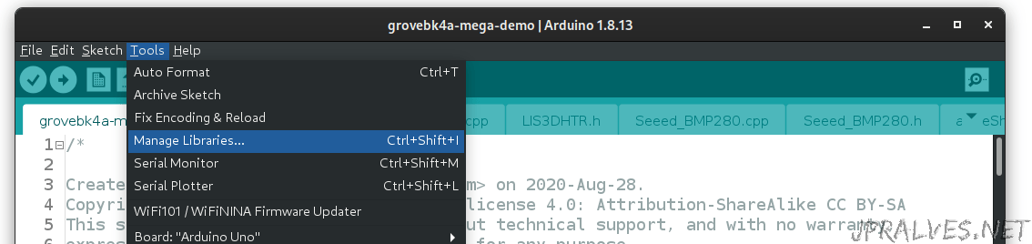
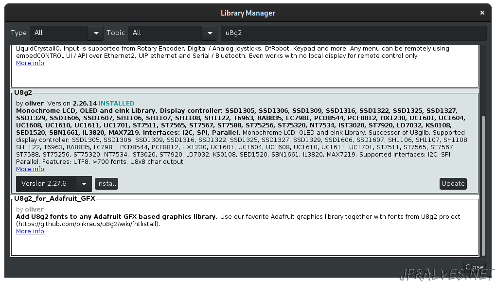
Press the Install button and it will be downloaded and installed from the Internet into the Arduino IDE.
More information about the setup and use of this library can be found on the u8g2 site.
The next step is to download and unzip the demo grovebk4a-mega-demo.
The source of the demo is composed of several files. Some with .ino extension (these are sketchs) that will be merged with the main ino file - grovebk4a-mega-demo.ino - and some h (header files) and cpp files that are libraries.
Arduino IDE will open them all in different Tabs.
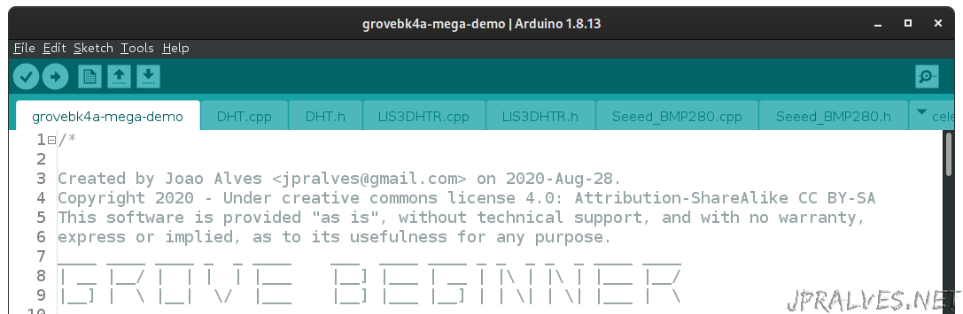
The files included are:
grovebk4a-mega-demo.ino- main file (contains the setup and loop routines).DHT.cppandDHT.h- Library for handling DHT11 module.LIS3DHTR.cppandLIS3DHTR.h- Library for handling LIS3DHTR module.Seeed_BMP280.cppandSeeed_BMP280.h- Library for handling BMP280 module.fix_fft.cppandfix_fft.h- Library for Fast Fourier Transformations.pitches_enhanced.h- File with Note Pitches - Used for playing sound.logoShow.ino- Code for displaying Logo in the OLED (Using the u8g2 library).buzzerShow.ino- Code for playing sounds in the Buzzer ModulecubeShow.ino- Code for displaying 3D Cube in the OLED.microShow.ino- Code for displaying audio spectrum from reading microphone.tempShow.ino- Code for displaying temperature and humidity from the DHT11 module.pressureShow.ino- Code for displaying pressure and temperature from the BMP280 module.aceleShow.ino- Code for display x, y, and z acceleration from LIS3DHTR module.lightShow.ino- Code for display readings from light module.trimShow.ino- Code for display readings from trimmer mopdule.
It is worth mentioning that some of the code was written by others and adapted to this purpose, many thanks to them for making it available on the Internet:
- DHT from Adafruit Industries (included in the official demo).
- BMP280 from Seeed Studio (included in the official demo).
- LIS3DHTR from Seeed Studio (included in the official demo).
- fix_fft from Tom Roberts.
- 3D cube from Colin Ord.
- audio spectrum analyzer from paul.
- code from the official Grove Beginners Kit demo.
- gauge from Giuseppe Bellomo.
The main code is simple to understand:
/*
Created by Joao Alves <jpralves@gmail.com> on 2020-Aug-31.
Copyright 2020 - Under creative commons license 4.0: Attribution-ShareAlike CC BY-SA
This software is provided "as is", without technical support, and with no warranty,
express or implied, as to its usefulness for any purpose.
____ ____ ____ _ _ ____ ___ ____ ____ _ _ _ _ _ ____ ____
| __ |__/ | | | | |___ |__] |___ | __ | |\ | |\ | |___ |__/
|__] | \ |__| \/ |___ |__] |___ |__] | | \| | \| |___ | \
_ _ _ ___ ____ ____ ____ ____ ____ ___ _ _ _ _ _ ____
|_/ | | |___ | | |__/ |__| |__/ | \ | | | |\ | | |
| \_ | | | |__| | \ | | | \ |__/ |__| | | \| |__| Mega Demo
Latest versions are available in https://jpralves.net
and https://github.com/jpralves/grove-beginner-kit-for-arduino.
This demo was created to show some of the possibilities to use the
grove modules that come with Grove Beginner Kit for Arduino.
Use the button from the button module to change to the next demo.
It uses several different libraries, all included except u8g2.
The code is divided in multiple files for better organization.
This sketch has 10 different demos:
- logoShow.ino with buzzerShow.ino using OLED display module and buzzer module
- cubeShow.ino - 3D rotating cube using OLED display module
- microShow.ino - three different displays of a audio spectrum analyzer using the grove microphone module
- tempShow.ino - displays temperature and humidity using DHT11 module
- pressureShow.ino - displays pressure and temperature using BMP280 module
- aceleShow.ino - displays x,y,z acceleration using LIS3DHTR module
- lightShow.ino - displays values of light sensor module
- trimShow.ino - uses gauge to display value of the trimmer module
It uses code from others worth mentioning:
- u8g2 library (https://github.com/olikraus/u8g2/wiki)
- DHT from Adafruit Industries (https://github.com/Seeed-Studio/Grove_Temperature_And_Humidity_Sensor)
- BMP280 from Seeed Studio (https://github.com/Seeed-Studio/Grove_BMP280)
- LIS3DHTR from Seeed Studio (https://github.com/Seeed-Studio/Seeed_Arduino_LIS3DHTR)
- fix_fft from Tom Roberts (https://github.com/kosme/fix_fft)
- 3D cube from Colin Ord (https://colinord.blogspot.com/2015/01/arduino-oled-module-with-3d-demo.html)
- audio spectrum analyser from paul (https://www.dellascolto.com/bitwise/2017/05/25/audio-spectrum-analyzer/)
- code from the official Grove Beginners Kit demo.
- gauge from Giuseppe Bellomo (https://github.com/olikraus/u8g2/blob/master/sys/arduino/u8g2_page_buffer/Gauge/Gauge.ino)
To build, the only requirement is to have u8g2 library installed in Arduino IDE.
Tested with Arduino IDE 1.8.13 and Seeeduino Lotus (Arduino Uno compatible).
*/
#include <U8g2lib.h>
#include <Wire.h>
#include "DHT.h"
#include "Seeed_BMP280.h"
#include "LIS3DHTR.h"
#include "fix_fft.h"
#include "pitches_enhanced.h"
const byte trimPin = A0;
const byte soundPin = A2;
const byte lightPin = A6;
const byte dhtPin = 3;
const byte ledPin = 4;
const byte buzzerPin = 5;
const byte buttonPin = 6;
const byte altledPin = 13;
DHT dht(dhtPin, DHT11);
LIS3DHTR<TwoWire> accelemeter;
BMP280 bmp280;
U8G2_SSD1306_128X64_NONAME_1_HW_I2C u8g2(U8G2_R2, /* reset=*/U8X8_PIN_NONE);
byte stateMode = 0;
void setup() {
Serial.begin(115200);
pinMode(soundPin, INPUT);
pinMode(buttonPin,INPUT);
pinMode(altledPin, OUTPUT);
pinMode(ledPin, OUTPUT);
if(!bmp280.init()){
Serial.println("bmp280 init error!");
}
//accelemeter.begin(Wire);
accelemeter.begin(Wire, LIS3DHTR_ADDRESS_UPDATED); //IIC init
delay(100);
accelemeter.setOutputDataRate(LIS3DHTR_DATARATE_50HZ);
if (!accelemeter) {
Serial.println("LIS3DHTR didn't connect.");
}
analogReference(DEFAULT);
u8g2.begin();
}
// List of demos:
typedef void(*callback_t)(void);
callback_t funcShow[] {
&logoShow, &cubeShow, µShow1, µShow2, µShow3, &tempShow, &pressureShow, &aceleShow, &lightShow, &trimShow
};
void loop() {
if (digitalRead(buttonPin) == HIGH) {
while (digitalRead(buttonPin) == HIGH) delay(10);
stateMode = (stateMode + 1) % (sizeof(funcShow)/sizeof(funcShow[0]));
}
funcShow[stateMode]();
}
// Sketch uses 28560 bytes (88%) of program storage space. Maximum is 32256 bytes.
// Global variables use 1178 bytes (57%) of dynamic memory, leaving 870 bytes for local variables. Maximum is 2048 bytes.
The code in the setup (which run once - at boot) is responsible for initializing all the modules and pins that require initialization.
The code in the loop (which will run indefinitely until the board is disconnected from power) will check to see if the button is pressed and moves to the next demo. An array of functions provides the order and location of the several demos.
The structure of most of the demos that require interaction with an OLED interaction are created like the following one:
void someShow() {
  // Reads and calculates some information from modules.
  // ....

  // initializes the OLED display
  u8g2.firstPage();
    do {
      // primitives for writing to the screen.

    } while(u8g2.nextPage());
}
This is the most efficient way to preserve RAM and display graphics in the OLED display module.
I’ve ordered the demos according to the complexity of them from the simple to the advanced:
- Simple:
- logoShow - Displays a logo and some text.
- tempShow - Reads a DHT11 module and displays its values.
- pressureShow - Reads a BMP280 module and displays its values.
- lightShow - Reads an analog module and displays its value.
- Intermediate:
- acceleShow - Reads a LIS3DHTR module and changes the value of an x,y point according to the acceleration of the x,y,z read.
- buzzerShow - uses a modified version of the play melody sketch to save memory - uses PROGMEM to store the static information.
- Advanded:
- cubeShow - Calculates the edges of a cube in a certain angle and draws those lines. The cube displayed is apparently rotating.
- microShow - Reads analog information from the microphone Module and after applying a Fast Fourier Transformation displays the resulting information in three different ways: as dots, as bars, as a graph.
The demo works using the button module to cycle between the different demos.
This demo can be used in a “Normal” Arduino, if you have the modules to work with it. The process of adding or removing a demo is just change the array defined in this lines:
typedef void(*callback_t)(void);
callback_t funcShow[] {
&logoShow, &cubeShow, µShow1, µShow2, µShow3, &tempShow, &pressureShow, &aceleShow, &lightShow, &trimShow
};
The program will adjust itself to having more or less demos.
It was very fun to create this demo for this specific purpose.
The demo is available in the link that is provided above, but is also available in the github project created for maintenance purposes.
Last thoughts
One of the more interesting features of the KIT its the fact that you can play with it without single cable (well, besides the USB cable). And that is not common in this type of Kits.
Of course I consider this Kit a learning kit and for that purpose it will work very well. The fact that it is not complicate to find other grove modules to be able to do other stuff is also an important factor to consider.
But the Seeeduino Lotus is also Arduino UNO compatible which means that every Arduino UNO shield out there will work with the this board.
Although it is recommended that, at that time you break the board out of the package.
You can even use non-grove modules, since the Arduino UNO headers are available.
The price of the Kit is just right.
Of course nothing is perfect and I’ve seen that there were lots of thoughts about the usage of the pins by the modules. But some improvements could be made:
- Attach the LED module to a PWM pin (Like D10)
- Move the Buzzer Pin to D11
Maybe these small issues be solved in a later version of the Kit.
Useful links
Special thanks
Last, but not least, I would like to thank seeed studio for providing me the chance to test this Board and making this useful article available to everyone.