
“Control all the appliances by just one tap. An IoT based Smart appliance controller using ESP-01
Story:
1. ESP-01:
Basically, it is the first wireless device in a small module, which was first used as wireless interfacing with the Arduino prototyping board. After some years later, it became a small standalone wireless module that acts as a micro-controller as well as a wireless device. It consists of two GPIO pins that can be triggered as programmed from the Arduino IDE.
2. Why this project?
I chose this project because as the time is advancing, people are becoming more and more dependent on the technology. With the advent of 5G, most of the technology is transforming from normal controlling hardware to IoT based hardware. People in recent years used to control the light by a simple switch, now most of them are controlled by using IoT hardware, some of the IoT devices are capable to control from access point based programming, this helps to control your appliance just using a smartphone, WiFi, and software that helps to control the IoT hardware from another city.
3. Project Detail:
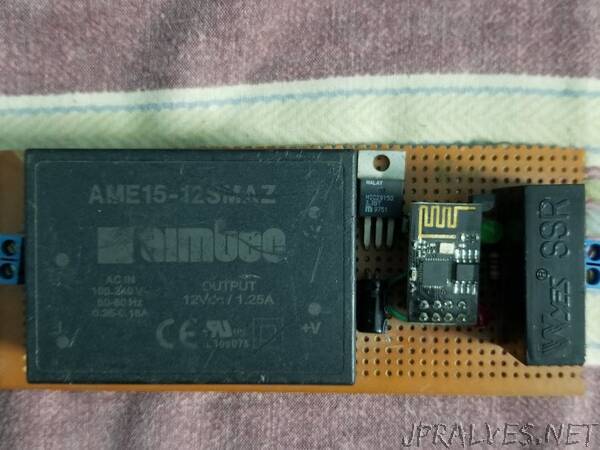
This project is my second IoT based project that was built to any appliance if the latest version of theesp8266 device is used then it may have more GPIO pins that can control more devices very easily. In this project, I have used one GPIO pin to control the output relay.
Since the voltage required by the ESP-01 is about 3.3V, therefore it can’t be used to turn on or turn off the relay. For this, I have used a small 6 pin optocoupler that isolates the output part from ESP-01, this is a perfect option because it helps to prevent surge protection.
Pin 1 of the optocoupler is connected to the cathode of the red LED, and a red LED is directly connected to the 3.3V linear regulator, pin 2 of the optocoupler is connected to the GPIO 2 pin, the pin 4 of the optocoupler is connected to the base of the NPN transistor through 1K ohm resistor, and finally pin 6 of the optocoupler is connected to the main supply which is coming from the 12V power supply.
As for the relay, one pin of the coil is connected to the 12V power supply and another pin of the coil is connected to the collector pin of NPN transistor, the emitter pin of the NPN transistor is connected to the GND rail.
The reset button is connected for the precaution, that if the hardware malfunctions.”