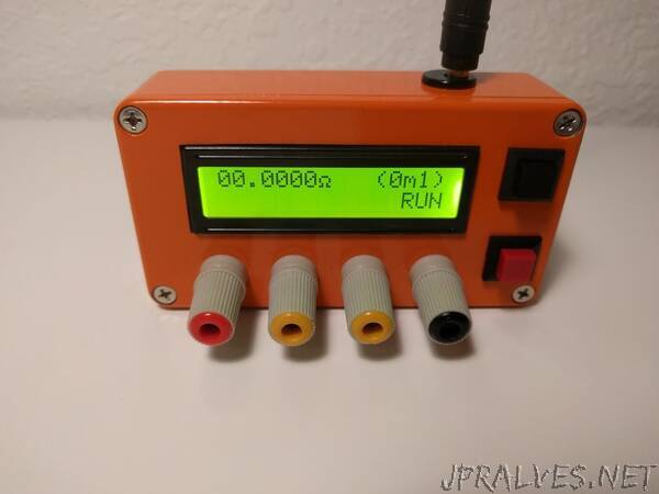
“A milliohm meter is a device used in determining the resistance of small resistors, PCB traces, motor coils, inductance coils, and transformer coils, or calculate things like the length of wires. It provides a resolution, not built into regular multimeters, making it easy to get accurate readings in the milliohm range.
There are quite a number of Miliohmeter builds on the internet, but today’s tutorial will chronicle the efforts of instructable user Danielrp. Daniel’s version of the meter is based on a precision current sink and a high-resolution ADC controlled by an Arduino Nano. The current sink is based on the LT3092 precision current source/sink which, using a network of resistors and transistors is set to function as a sink. For the ADC, the high resolution, MCP3422A0 I2C ADC is used. Just one of the channels of the ADC is used, and it is connected differentially to the Resistor under test “S+ S-“. The MCP3422 is configured as 18bit but as S+ is always going to be greater than S-, the effective resolution is 17bit.
To reduce the influence of the resistance of the test leads on the measurement, the devices use Kelvin connectors as leads to connect the resistor under test to the measurement point.”
