
“Get cozy.. the instructable youre about to read is something I have been working on for a year and a half (mostly during the night and weekends) so this read might be a bit longer than one would expect. Though there is a tremendous amount of work in this project already, there is still room for improvement. If you have ideas that can make this home automation tool better, please let me know!
Motivation and Short Description
The motivation came when a friend started talking about a small aquarium automation tool he built with Arduino. We both believed that through his knowledge in fish, plants, aquariums and electronics, plus my knowledge in embedded systems, electronics and programming we can make a great gadget that can help aquarium enthusiasts spend more time with aspects they like most, leaving the lights, filter, skimmer and others to be switched automatically through a predefined schedule. My very first tries were Arduino based. My antipathy towards the Arduino quickly resurfaced as the software started to become more and more unstable until the point where two consecutive flashings resulted in completely different behavior. When I read that using more than 75% of RAM can result in such instability, I decided to take matters into my own hands and make the main and control boards myself.
After multiple sessions of brainstorming and consultation, I began working on the draft of the Main Unit’s schematic – initially on paper. As the requirements got to a somewhat final shape, I started building up the schematic and footprint library in Altium Designer with the components I knew I needed. In two weeks I had the first draft of the schematic in Altium designer and began routing a PCB. As I am writing this instructable there is still one PCB I have to design and build, I will try to make a speed-up video so you can see how schematic capture and PCB routing works in Altium. I decided against making the PCB myself, as it grew a bit too complex for home etching. When the boards were ready, I sent the production files over to the guys from Elecrow – in about two and a half weeks I got them through DHL and began the assembly.
With the Main unit’s assembly approaching finalization, I started working on the LCD and the user interface. After a couple weeks passed by with me trying to use standard toolbox items (buttons, textboxes, poorly rendered fonts) to create the UI, I realized that – no matter what I’d do – it’s just too rough and not one bit appealing. It was this moment that I began using pictures as buttons and as other UI elements. This required some amount of graphical design work, the pictures had to be of exact sizes, and Microsoft Paint simply wasn’t enough. I got help from another friend who had quite some experience in this, but since I was available for this project mostly on weekends or during the night I had to install a graphical design software so I can immediately edit pictures when I needed to. Inkscape was chosen for graphical design. Wiring diagrams, PCB symbols, and UI interface objects were all made with help from tutorials and existing SVGs.
As soon as the Main unit got a working user interface, I started thinking about the second sub-project: the Control Box. Incredibly, this PCB was fully functional after assembly. I tested the code I wrote before “blind”, and after maybe 5 small changes and typos in the code, the PCB was considered to be OK. To be honest, this may be due to the fact that there are many similarities between the two projects. The two most important similarities are related to the main MCU and the Radio board. I thought that having the same processor and the same Radio chip will help speeding up software development; this way the radio control code can be exactly the same on both the Main unit and the Control box PCB! After the radio link was up (and boy, did this take me some time..) I worked out a simple communication protocol so the two units can talk. This communication protocol is – at the moment – maybe a bit too simple. A handshaking mechanism and some message CRC firmware bits are already on the way.
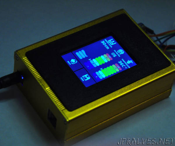
Next thing was to wire the Control box PCB together with the relay board, a 12V power supply, power outlets, H-bridge drivers, and aviation sockets. Once this was ready, I could roll the first tests to figure out what is working and what isn’t. To do this, I soldered a patch of RGB strip and a small aquarium pump to an aviation plug. Initial tests got me pretty happy, for example the LED strip lit up at first test. After eliminating a few bugs in the communication protocol I got in control of the RGB LED strip. There was a step-back to UI design at this moment, as I had to figure out a clever way the user could schedule color transitions. After many tries I came up with the RGB menu you can see on the pictures or in the Nextion Project files. The pumps had to come next. I am currently at testing phase with many features, but the thing works! I hope I’ll still have time to tackle some more of its current problems after I’m done with describing the steps.
Having designed three PCBs for this project (actually five, with the Main board having three revisions) it is quite the candidate for the PCB contest in progress here, on the instructables website. I have plans on developing this project to a phase where users could buy it, so I am shooting for the stars, hoping to win the CNC router so I can machine the enclosure instead of piling and sanding for many-many hours.
That’s about the short of it! Keep reading to find out more about the technical details!”