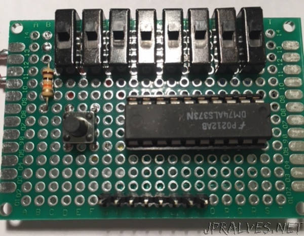
“When we work on electronic circuits, there are some tools that get frequent use. Things like multi-meters, oscilloscopes, and waveform generators. Working with digital circuit has some use for those, but brings with it different requirements that require different tools. We’ll have a look at some of these. These are fairly simple and can be made quite easily.
Logic Probe by Dave Astels
With analogue circuits, we need to measure voltages, currents, waveforms, and the like. With digital circuits we often only care whether a signal is logic high or low.
A logic probe allows you to peek in at logic signals inside an operating circuit on an as-desired basis; no need to wire up LEDs to monitor signals (although that’s sometimes exactly what you want, and we’ll cover that later in this guide.
You connect the probe’s Vcc and ground to their counterparts in the circuit being tested and you use the probe connection to touch points in the circuit where you wish to know the logic level. Be careful not to short connections (e.g. adjacent pins of a chip) with the probe. With digital circuits nothing really bad should happen (usually), but you won’t get an accurate measurement.
You can buy a logic probe for $25-$50 from Amazon, Mouser, or the like. But we’re makers and there’s not a lot to it. So let’s make one.
After looking around the internet for a simple, cheap, and easy to build probe I found the article below. It describes (including schematic and build suggestions) a simple transistor based logic probe.
Operation
You start by connecting the 5v and ground connections to the 5v and ground of the circuit being tested. If you are powering the probe with another supply, the will need to have a common ground as usual. Then you simply touch the probe connection to the signal you want to check. If it is a logic low (< ~1.2v) the L LED will light (I use red) and if it is a logic high (> ~2.4v) the H LED will light (for which I use green). If the probe is unconnected, neither LED should be lit.*
If the signal is switching between high and low the LEDs will flicker between the two, clearly toggling back and forth if the frequency is low, and both glowing at something less than full brightness if the frequency is higher. In this case the relative brightness can give you an idea of the duty cycle even though you can’t observe it directly.
How it works
When the probe is unconnected, R1 and R2 set the voltage at the base of T1 such that it turns on just a bit which causes enough voltage drop across R5 to turn T3 turn on which keeps T4 off, meaning LED2 is dark. At the same time current running through T1 (and R3 and R5) is small and results in a small enough voltage across R3 to keep T2 from turning on, keeping LED1 dark.
When the probe is at a logic high (>~2.4v) T1 is held strongly on, keeping T3 on which keeps T4 off and LED2 dark as before. In this situation the probe voltage will be higher than when unconnected so the current through T1, and hence R3 will be higher. This means a bigger voltage drop across R3, which lowers the voltage at the base of T2 making it turn on (notice it is a PNP transistor, not an NPN like the others so it sort of works backwards), lighting LED1.
The final case is when the probe is at logic low (<~1.2v). This will cause T1 to turn off, turning off T3. This, in turn, lets the voltage at the base of T4 rise (though R7 and R9) enough to turn it on causing current to flow through LED2, lighting it. There’s no current flowing through R3, thus no voltage drop and T2 stays off, keeping LED1 dark.
Note that the BC177 (or BC557) can not be replaced with a 2N3906. I tried since I had 3906s in stock.
One unanticipated feature of this probe is, since it is transistor based and not TTL based, it works fine with 3.3v circuits. You do have to power it with 5v, though. And make sure you have connected the grounds together.”
