
“Basic code to make Arduino communicate with ILI9341.
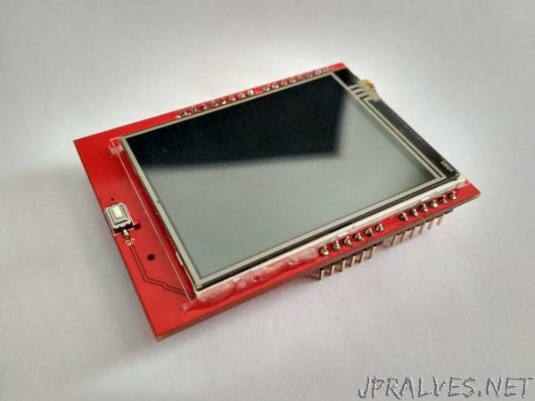
Colorful, 18-bit 262,000 different shades4-wire resistive touchscreen8 bit digital interface, plus 4 control lines
Download ILI9341 Datasheet:https://www.pdf-archive.com/2018/01/07/ili9341/
The shield connects ILI9341’s data pins 0-7 to Arduino digital pins 2-8 (allowing parallel communication, not SPI). ILI’s RESET goes to pin to Arduino analog pin A4.CS (chip select) to A3. RS (CD command/data) to A2. WR and RD to A1 and A0.
ILI9341 is integrated inside the display. It drives the display and has nothing to do with touchscreen (Although the shield connects some pins of ILI9341 together with pins of the touchscreen).
You have first to send a command to ILI and then write or read data/parameters. CS pin has to be LOW during the communication, WR rising from LOW to HIGH tells to ILI to read byte on data pins. (see code ILI9341_1.ino)
ILI9341 interpretes input byte as command (if RS=0) or as data/parameter (RS=1). (see code ILI9341_2.ino)
To read a byte from ILI after sending a read command (e.g. 09h - Read Display Status) set RD from HIGH to LOW, so ILI9341 outputs data until RD returns HIGH. (see code ILI9341_3.ino)
To draw a rectangle (or just one pixel) on the screen you have to tell to ILI the area (start_column, end_column, start_row, end_row, commands 0x2Ah and 0x2Bh) you want to draw. Then command 0x2Ch. Then send in sequence for every single pixel in the area a value of the color to display. The color has 2 byte format.
The touch screen is attached on the surface of the display. It connects through 4 wires, which share arduino pins 8, 9, A2, A3 with ILI. So you can’t write to LCD display and read the touch screen in the same time.
https://www.pdf-archive.com/2018/01/07/touchdetect/
Wikipedia:Touch-screen devices using resistive technology, a two-dimensional membrane potentiometer provides x and y coordinates. The top layer is thin glass spaced close to a neighboring inner layer. The underside of the top layer has a transparent conductive coating; the surface of the layer beneath it has a transparent resistive coating. A finger or stylus deforms the glass to contact the underlying layer. Edges of the resistive layer have conductive contacts. Locating the contact point is done by applying a voltage to opposite edges, leaving the other two edges temporarily unconnected. The voltage of the top layer provides one coordinate. Disconnecting those two edges, and applying voltage to the other two, formerly unconnected, provides the other coordinate. Alternating rapidly between pairs of edges provides frequent position updates. An analog-to digital converter provides output data.
First we need to detect if there is a touch. So we connect both wires of one layer/membrane, e.g. X to ground (LOW from ardiuno pins set as output) and one wire from layer Y to pull-up resistor (setting corresponding arduino pin as INPUT_PULLUP). Reading the second wire of Y layer we get HIGH if there is no touch (because of pull-up) and LOW if there is a touch (because of contact with grounded X layer).
Then we need to read a position of a touch. So we set one of the X wires to HIGH (which one depends on on which side of touch screen we want to read min/max value; see variant A/B in the code) and we read analog value on Y. The value should be in the range 0-1023, but touchscreen I tested returns 110-910 (So it need to be calibrated - run ILI9341_7.ino). Then we apply LOW-HIGH on Y layer and read analog value on X.
Touchscreen I tested sometimes wrongly detects a touch, outside of the touched point. To prevent this I added some delays and the X and Y analog value is read repeatedly and touch is approved only if values do not differ (a lot).”