
“Maze-solving robots originate from the 1970s. Since then, the IEEE has been holding maze solving competitions called the Micro Mouse Contest. The aim of the contest is to design a robot that finds the midpoint of a maze as quickly as possible. The algorithms used to quickly solve the maze typically fall into three categories; random search, maze mapping, and right or left wall following methods.
The most functional of these methods is the wall following method. In this method, the robot follows the right or left side wall in the maze. If the exit point is connected to the outer walls of the maze, the robot will find the exit. This app note uses the right wall following method.
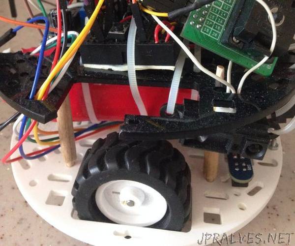
Hardware
This application uses:
2 Sharp analog distance sensors Tracker sensor Encoder Motors and motor driver Silego GreenPAK SLG46531V Voltage regulator, robot chassis.We will use the analog distance sensor to determine the distances to the right and front walls. The Sharp distance sensors are a popular choice for many projects that require accurate distance measurements. This IR sensor is more economical than sonar rangefinders, yet it provides much better performance than other IR alternatives.There is a nonlinear, inverse relationship between the output voltage of the sensor and the measured distance. The plot showing the relationship between the sensor output and the measured distance is shown in figure 1.
A white line against a black color ground is set as the target. We will use the tracker sensor to detect the white line. The tracker sensor has five analog outputs, and the outputted data is influenced by the distance and the color of the detected object. The detected points with higher infrared reflectance (white) will cause a higher output value, and the lower infrared reflectance (black) will cause a lower output value.
We will use the pololu wheel encoder to calculate the distance the robot travels. This quadrature encoder board is designed to work with pololu micro metal gearmotors. It functions by holding two infrared reflectance sensors inside the hub of a Pololu 4219mm wheel and measuring the movement of the twelve teeth along the wheels rim.
A motor driver circuit board (L298N) is used to control the motors. The INx pins are used to direct the motors, and the ENx pins are used to set the speed of the motors.
Also, a voltage regulator is used to reduce the voltage from the battery down to 5V.”