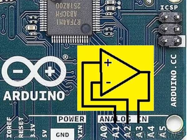
“Using analog components in a digital environment is quite unusual and it is difficult to find information about. First steps are shown here.
When the revision of ARDUINO UNO R4 was advertised all the distributers did not hesitate to mention the built-in OPAMP though no further information about it was available, no schematics, no tutorial, nothing. Only some month later, a few lines of code were published (see credits), and the only application given was a voltage follower which is completely useless.
The Hardware Part
What can be done with some additional passive components is a filter that amplifies or rejects certain frequencies of an analog signal. Of course, this can be done by code but this may use a lot of processing time. Analog filters operate with the speed of light (nearly).
Instructions on how to implement filters can be found online easily (see credits). But you have to consider that operational amplifiers often need a positive and a negative supply voltage which we do not have. So we have to feed half of +Vcc to the non-inverting input (+), connected to A1, That is why you find two resistors (same values) between +Vcc and GND. We choose 10 kOhms for R1 and 22 kOhms for R2. The values of C1 and C2 depend on which frequencies you are interested in. We choose 100 nF.”
