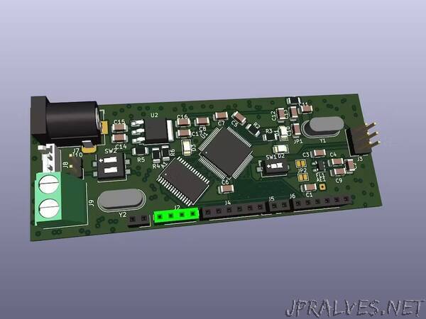
“This project documents the development board’s schematic and hardware layout.
An ATmega128RFA1 board has the following features;
Arduino-compatible with R3 Form Factor
Onboard chip antenna
33 Digital I/Os
SPI, TWI, and UART interfaces
8 Analog Inputs (10-bit)
16 MHz operating frequency
Pre-programmed ATmegaBOOT bootloader
On-board 3.3V regulator
ATmega128RFA1 with 6 Timers, 128 KB Flash, 16 KB SRAM, 4096 Bytes EEPROM
2.4 GHz RF Transceiver
Requirements
To develop an ATmega128RFA1 board, gather SparkFun FTDI breakout, headers, power connector, and soldering tools for assembly.
What is an ATmega128RFA1?
Two parts are combined to make an ATmega128RFA1 board; both the half RF transceiver and the half microcontroller.
Half Microcontroller
In other words, it is known as the ATmega128, which is an enduring tradition of Atmel AVR microcontrollers. This microcontroller has a 128kB flash, numerous I/O pins, ADC, and more.
Half RF Transceiver
The unique ATmega128RFA1 transceiver, operating on a 2.4GHz wireless radio chip, enables communication within a 75m radius at 2 Mb/s. Supporting IEEE 802.15.4, it forms a PAN like Bluetooth but with a lower data rate (around 250kbps). Ideal for low-level, low-power, and low-range device communication, it suits various embedded applications like weather stations or remote coffee machine activation.”
