
“This is part 2 of my “more reliable keypad”. In order to reduce the number of required IO Lines to drive the keypad, use I2C..
n a previous post this month I introduced my 4×4 matrix keypad. That keypad was designed to be directly interfaced to a microcontroller’s GPIO pins or alternatively to an IO expander chip like the PCF8574. That design, while working very well had the problem of requiring 8 GPIO pins to function correctly. GPIO pins on a microcontroller can be considered very precious resources, and it should then be logical to assume that we should find a way to use these GPIO pins in a more conservative way, to allow us to interface more peripherals.I solved this problem by integrating the keypad with an IO Expander on the same PCB. That will allow us to get away with using only 2 GPIO pins, and also open up the option of adding more keypads to the I2C bus, in the event that we need that many keys for a particular project.
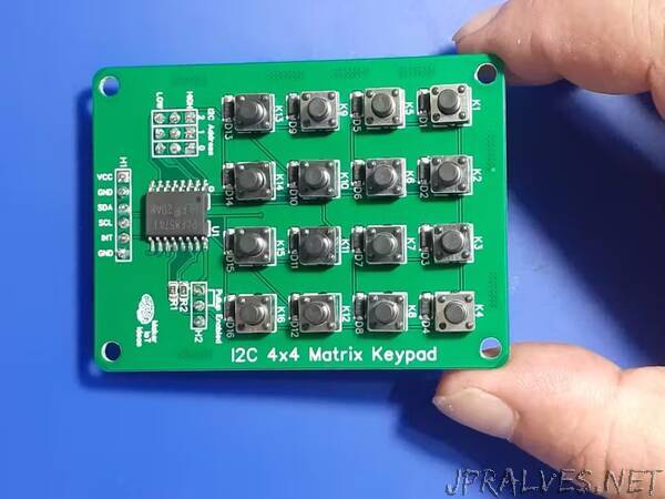
Looking closely at the schematic, we can see that it is exactly the same basic keypad circuit that I used in the initial design. The only difference is that in this design, I have integrated a PCF8574 directly onto the PCB.Some additional features include selectable I2C Pullup resistors ( usually my microcontroller development boards already include those) that can be activated with a jumper when needed. There are also a set of address selection jumpers, making it possible to stack keypads together into a bigger keyboard if you require something like that. Note that, in this version of the hardware, I did not include headers for stacking.
The keypad can be powered by a DC power source of 3.3v to 5v.”