
“Do you have rooms in your house that are colder than other rooms in the winter? If you have air conditioning, are those same rooms warmer than other rooms in the summer? It’s common for that to happen to rooms farthest from the blower on the furnace or air conditioner. You can buy booster fans that sit on top of or under registers to blow more air into those rooms.
With this project, you can make your own booster fans with behavior that is completely under your control.
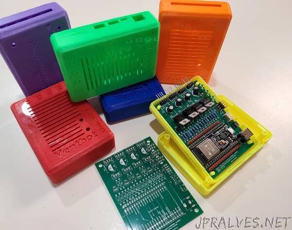
The idea is to use commonly available and inexpensive PC case fans to do the work. A small circuit board and microprocessor provide the smarts. When the furnace or air conditioner is blowing warm or cool air into the room, the Ventbot automatically turns the fans on to provide a boost. When the furnace or air conditioner stops blowing, the Ventbot turns the fans off. Once you have it built and installed, you can just set it and forget it.
There are a lot of interesting things to consider in the design, but I’ve done a bunch of that thinking and deciding for you. All of the design files and software source code are freely available under open source licensing, so you can do things differently if you want to. I would be interested in hearing any suggestions or ideas for improvements (you can leave comments about that here or in one of the project reference sites mentioned below).
The description of this project is a bit lengthy. If you are already a maker of sorts, some of the description will be an over-explanation of obvious things. I wanted to provide enough details so that someone who isn’t a maker, or who hasn’t done these particular things, will have the information to actually be able to do it. At a glance, it seems complicated, but each step is straightforward.
The minimum skills you will need are:
Simple electronic soldering (very basic; even if you are a beginner, you shouldn’t have much trouble)
3D printing for the enclosure and brackets (if you don’t own a 3D printer and don’t have access to one, there are services where you can upload files and have things made and shipped to you)
Simple computer skills for uploading firmware to the board.
The master repository for all of the hardware and software design files is here: https://gitlab.com/wjcarpenter/ventbot If you want to know more about my journey in designing this thing, you can read all about it here: https://hackaday.io/project/186808. (You don’t have to read that in order to build one, though. It’s even longer and has more tangents than this Instructable.)
The list of supplies and the set of steps below look long and a bit daunting. That’s because there are some options and other things to think about when you gather your parts. I put a lot of information into the supplies section and the assembly steps, so don’t skip over it. I suggest you read through the whole thing before shopping for any parts. Definitely read through all of the “Plan” and “Decide” steps below before obtaining any parts. Otherwise, you might waste a little money getting things you don’t need. Nobody wants that.
Here’s the overview of how this fits together:
- There’s a printed circuit board (PCB) with various components to be placed on it.
- One of those components is an ESP32 microprocessor module. You’ll be putting custom firmware onto that module.
- There are connectors on one end of the circuit board for connecting the cables from the fans.
- There is a temperature sensor that is connected to the circuit board with some wires.
- An enclosure for the project can made on a 3D printer.
- Brackets for holding the fans together and for installing them inside the vent cavity can be made on a 3D printer.
- You might want to do some simple calibration and update the custom firmware once you have everything assembled.
- Your friends and family will think you are a genius (this step is optional).
Note: A few of the pictures of the PCB and a few of the diagrams show v2023-01-13. I made some small modifications to produce PCB v2023-02-14. Since those changes were not pertinent to the things being shown in the older images, I didn’t update them. The v2023-02-14 version is the definitive version and is what all the steps actually describe.
Supplies
Let’s start with the tools, since that’s simpler.
- Access to a 3D printer (or a 3D printing service) for making the enclosure and mounting brackets
- Simple soldering tools: soldering iron, solder, etc.
- Simple and common hand tools. A pair of diagonal cutters for trimming component leads is essential.
- A computer with a USB port for uploading the firmware. Later firmware updates can be done over wifi, and you might not need to do any.
Now for the parts, which is a kind of lengthy list.
The circuit design can work with up to 4 fans, but both the circuit board and software can work with fewer fans. Both the circuit board and the 3D printed case have markings to indicate which fan is which. Obviously, you need at least 1 fan, or it’s pointless. If you do use just one fan, it should be Fan 1 to minimize confusion. Other fans can be any combination of Fan 2, Fan 3, or Fan 4. The software will automatically detect which fans are present. Many of the parts are “per fan”, so if you don’t use a particular fan position, you can leave some parts unpopulated on the board. There are also circuit options to have some things for other fans controlled by Fan 1, in which case you can leave even more parts off the board. These optional parts are indicated in the descriptions below.
Depending on the choices you make about optional parts, how good a shopper/scrounger you are, and what you might already have laying around, I think the total cost ought to be US$60 or so. You can buy a ready-made booster fan for around that price, but you’d be missing the adventure of making it yourself. You will also have more control with one you build yourself. (Confession: I was originally going to buy a booster fan, but I couldn’t find them available during the time in the pandemic when I was thinking about this. That’s why I went off on this design tangent. The commercial units are more readily available now, but so is this design.) The per-item prices for some things would go down quite a bit if you bought a bunch of them, so it gets a bit cheaper if you are building multiple Ventbots. I needed five Ventbots for my house.
The parts listing in a bill of materials (BOM) produced by the KiCad design software, and then annotated by me, can be found here (same content; different formats): BOM.csv and BOM.xlsx, or on Google docs at ventbot BOM.
These estimates are more like guesses, informed by what I have paid for parts like this recently:
- ESP32 module: US$10 each
- Circuit board manufacture: US$15 for 5-10 boards total
- BMP280: US$3 each
- Fans: US$7 each
- Capacitors, resistors, transistors, connectors: under US$10 for everything
- Voltage converter: US$3
- Material for 3D printed parts: negligible
- 12vdc power adapter: US$7 each
Most of these parts are just mentioned briefly here so you can get a quick idea of what you will need. Be sure to read through the “Plan” and “Decide” steps for additional comments about some of them (for example, what substitutions you might make, what they actually do, etc) and for parts you can omit if you are not using all 4 fans. For handy reference, the “Decide” steps are intermingled with the assembly steps. At least, I hope that’s handy and not confusing. For each “Decide” step, there is a suggestion for what to do if you’d rather not think about it too much. (I’ve already thought about it way too much.)
- Circuit board: It’s theoretically possible to wire the entire thing up on a breadboard or protoboard. That’s how I tested the design. However, that’s an untidy mess of wires, and it’s better to have a manufactured circuit board. (Most of the PCB manufacturers have the same prototyping prices for up to some number, typically 5 or 10, of the same board. Even if you don’t plan to use them all, you might as well get them. You might make some mistakes, you might have friends who would be interested, or you might someday use them for some other ESP32 project.)
- Enclosure: The repository at https://gitlab.com/wjcarpenter/ventbot includes design files for a 3D printed enclosure. See the step about the enclosure below.
- Fan mounting brackets: The repository at https://gitlab.com/wjcarpenter/ventbot includes design files for 3D printed brackets for mounting the fans. See the step about the brackets below.
- PC case mounting screws: You might want more screws for mounting the fans than usually come with a new fan. Or you might be using some fans that you have laying around, and the screws might have wandered away.
- Fans: The design allows for up to 4 PC PWM case fans to provide the boost. How many you use will be limited by the dimensions of your vent openings. See the “Measure Your Vents” step below.
- Resistors:
- 4.7k ohm: (4 per fan)
- 27k ohm: (1 per fan)
- 10k ohm: (1 per fan)
- Electrolytic capacitors: 10uF: (1 per fan)
- Transistors
- NPN bipolar transistor: (1 per fan)
- N-channel MOSFET: (1 per fan)
- Voltage regulator: Switching voltage converter; or 7805 linear regulator with optional heatsink
- Jumpers and pin headers: (optional)
- 3-pin 0.1in pitch pin header: optional, up to 6
- 2-pin jumper blocks: one for each 3-pin header
- External connectors
- Fan connectors: (1 per fan)
- I2C connectors: (at least 1 of the 3 choices)
- Power jack
- ESP32 module: There are a lot of ESP32 modules available with different sizes and configurations of pins. Makes sure you get the right one. The design uses ESP32-DevKitC V4 with a ESP32-WROOM-32D module. There are other variations that will work. The most important thing is to get the 38-pin version, and that the pin signals are the same as the ones the design uses, at least for the signals that are actually used. Even though it’s pretty old, you can still find ESP32-DevKitC V1, which has slightly different physical dimensions; it will still work and will fit as long as you pay attention to surrounding components.
- ESP32 extra pins: (optional)
- 1x19 0.1 inch pitch pin header, optional: J1, J2
- Temperature sensor: The part I use is Bosch’s BMP280 on a break-out board. They are commonly available and inexpensive. Without any changes, the firmware can alternatively use a BME280 sensor to also get relative humidity, though a BME280 is more expensive these days. For both BMP280 and BME280, the ones I have seen have all had an I2C interface, and some of them also have an SPI interface. This design uses the I2C interface. (You don’t need to understand much about that to build this.) The firmware also reads the pressure from the BMP280 or BME280, and the relative humidity from the BME280, but it doesn’t use them for anything beyond reporting them. In fact, the firmware will automatically try to find several different temperature sensors that ESPHome supports, but I have only tested BMP280 and BME280. You can even use yet a different temperature sensor if you are willing to modify the ESPHome configuration file for the firmware. That will be pretty simple if the sensor uses I2C and is already supported by ESPHome. I2C parts sometimes come in either 3.3v or 5v versions. You want 3.3v parts to be compatible with the ESP32 module.
- BMP280 sensor
- cabling: Wiring to connect the temperature sensor to one of the available I2C connectors on the board.
- Power supply: This is a commonly available 12vdc power supply with a 2.1x5mm barrel connector. 1 amp at 12vdc should be more than sufficient. Since this will be plugged in all the time, I recommend that you use only a quality part that is UL or ETL rated. You probably want to see if you can get one with a cord long enough to reach from the mains outlet to the location of the vent, plus a little bit (to avoid the need for an extension cable), but it’s hard to find them with cords more than 3-5 feet (1-2 meters) long.”