
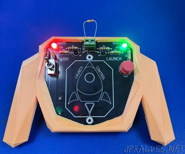
“This is a handheld model rocket launch controller with 3D printed game controller like handles.
I designed it with through hole components so that younger scouts could solder it on their own.
Cost is about $15 per unit when made in sets of 10, shipping cost was a large factor.
All documentation is stored on Github at https://github.com/RWilkus/Launch-Controller-1
Go to link and download zip file with all design files.
Circuit Design Background:
The design started after reading through this work by J.R. Brohm. In the end of his testing, he proposed a transistor based circuit to lower the amount of current required to do an ignitor continuity check. Since the transistor only needs a couple milliamps of base current to switch, it lowers the current being passed through the ignitor and therefor reducing the possibility of random ignitions. The first transistor, Q1, is the implementation of his purposed circuit.
The second transistor, Q2, is used as a high current switch since the launch button, SW2, can only handle 100 mA and the ignitor needs in excess of 1 amp to ignite. The launch button was selected mainly for its low cost and style.
Circuit protection is handled by two methods. Over current protection is handled by PTC1 which is a thermal fuse that will trip and protect the downstream circuitry. This could happen if the ignitor clips are touching when the launch button is pressed. This will reset if the arm switch is turned off. The second set of protection is formed by D1 and D2 which are transient voltage suppression(TVS) diodes that clamp higher voltage spikes from electrostatic discharge(ESD). I assumed this device will be handled by everyone and could have an increased risk of getting shocked. These diodes protect the transistors mainly because they are more prone to damage from high voltage transients.
Printed Circuit Board Layout:
Schematic capture and layout were done with Autodesk Eagle free version which allows for two layer boards. The entire bottom layer is a ground plane as seen by the dotted blue outline. The dotted red lines are oversized traces that will handle overcurrent events before the protection kicks in.
Simulation using LTSpice:
We found the Q1 base current was 1.2mA with a 4.7k resistor in series.
When the launch button is pressed, the voltage across the ignitor goes to near zero as the current increases to about 1.7A. This limitation is based on the series resistance of the batteries, printed circuit board, Q2, and the wire to the ignitor.”