
“As part 2 of my quest to build some “bench development PCBs”, This one adds CAN Bus support to the ATMEGA4808.
In This, Part 2 of my CAN Module series( Read Part 1 here), I will look at my recent modification of a previous ATMEGA4808 Development PCB to include CAN bus hardware. The ATMEGA4804 with CAN Bus development board is part of a set of “benchtop development tools” that I designed specifically to design some CAN Bus controlled Gadgets for use in my car…
The PCB is based on a previous project, in which we experimented with alternative chips to replace the ATMEGA328P.
As I was quite happy with the performance of this particular project, I thus decided to use it as the base for the CAN Bus module as well. The Added CAN Hardware adds only a few cm. to the board, keeping it quite compact, although, it will need a complete redesign once I finally get my gadgets finalised.
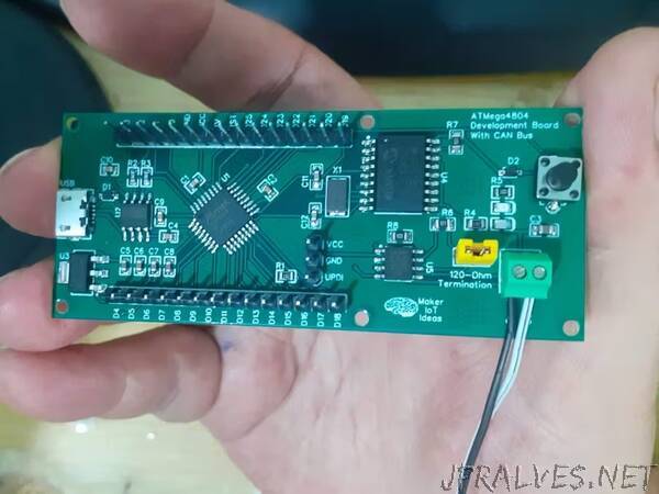
The ATMEGA4808 and its supporting components dominate the left side of the PCB, with a USB connector and a CH340N providing the possibility to upload code to the chip using the Optiboot bootloader. I would however caution you, as there seem to be quite a lot of counterfeit CH340N chips floating around, I received two bad batches already, and from reliable suppliers as well… seems there is something fishy going on in the factory?? Answers anyone?
The Right side of the PCB is dedicated to the CAN Hardware, with the MCP2515 and TJA1050 taking centerstage here. While quite old, the MCP2515 is still readily available for the time being and is also quite affordable. Since I had a few left over from previous projects, I decided to once again make use of what I had on hand. A 120-Ohm termination resistor ( selectable with a jumper), as well as a screw terminal connector, is provided. The board Reset button, as well as a power and user LED ( on D7), is also in that area of the PCB.
All GPIOs on the ATMEGA4808 were broken out onto header pins, to allow for maximum flexibility and access to features and peripherals on the chip.”