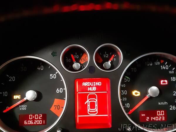
“Implementing my own Arduino CAN bus Shield and digital speedometer to car’s LCD-display in instrument cluster.
Start of the Project
It all started in the summer of 2020, when I bought an Audi TT 2002. Unlike my previous cars, it didn’t have a digital speedometer in the instrument cluster’s little LCD-display (Driver Information System DIS in Audi). Due to the lack of digital speedometer, I decided to implement it myself. To cut a long story short, I thought I could take advantage of existing GitHub-project and wrote the code for that setup first. Though I soon realized the setup used in the existing project was different to mine, so I had to start it all over.
Basic Idea
Audi TT’s DIS-display shows the radio station or the CD-track in the upmost third of the display. My plan was to replace the radio info with digital speedometer. From the previously mentioned project I found out that the radio sends information to the instrument cluster via three one-way data wires. When I pulled my radio out, I found out that my radio didn’t use these three wires, but CAN bus instead. My car had a Chorus-radio, and the older one with three wires was a Concert.
Audis with Concert
one-way data connection between the radio and the instrument cluster
three wires for data transfer (DATA, CLOCK, ENABLE) (I thought my car had these)
Audis with Chorus
two-way data connection (Half-duplex) between the radio and the instrument cluster implemented with CAN bus
data transmission rate 100 kbps (Infotainment CAN)
two wires for data transfer (CAN-High, CAN-Low) (My car had these)
Reading vehicle speed data
Before I tapped into CAN bus with Arduino, my plan was to acquire the vehicle speed signal from the radio’s GALA-wire (Graduated Audio Level Adjustment). GALA increases radio volume automatically according to vehicle speed. Since my car has CAN bus, there is no need for GALA-wire and the instrument cluster sends vehicle speed data on the bus every 200 ms. I’m planning to use these CAN-messages in my digital speedometer solution.
Designing Fault Tolerant CAN-shield for Arduino
After doing a little research on the CAN bus (especially in VW-group cars), I found out that the bus used in my car was a so called Fault Tolerant CAN bus. For me it meant that I couldn’t use off-the-shelf CAN-shields for Arduino.
I decided to design a circuit board for the CAN-shield and integrate my Arduino Nano into it. Main components needed for the CAN-shield were
MCP2515 Stand-Alone CAN Controller with SPI Interface (Easy to communicate with Arduino via SPI)
TJA1055 Enhanced fault-tolerant CAN transceiver
16 MHz Crystal Oscillator
resistors, capacitors and screw terminal block
circuit board
TJA-1055T Application Hints -document was useful when I dimensioned resistors and capacitors. I used Arduino CAN Tutorial when I drew the connections between Arduino and MCP2515.”
