
“I’m Cayden, an electrical engineer and transhumanist hacker. In this article, I explore the frustrations of repetitive manual tasks in PCB design and the benefits of automation. I demonstrate the automation of tasks such as connecting pins, generating test points and indicator LEDs, programmatically placing components, and autorouting.
Introduction
If I’m writing a program, I’ll write a function one time, then use that function every time afterwards. Usually, if problems arise over and over again, we solve them once really well, then we don’t solve them again.
Yet as an electrical engineer designing circuit boards, I often burn a lot of time on repetitive tasks. These tasks can get annoying - they’re something I’d rather automate.
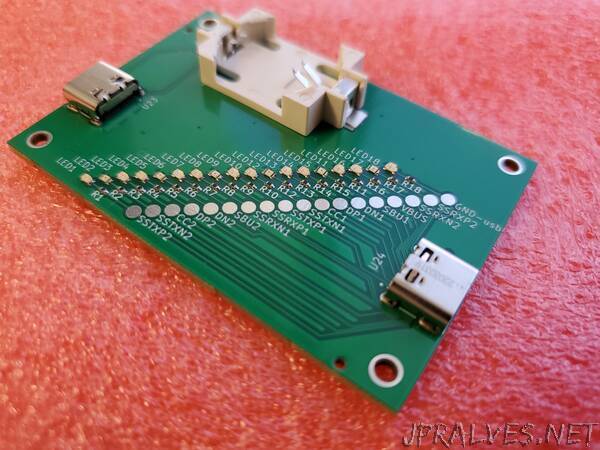
For example, to design a simple USB-C cable testing board I would have to:
- Calculate and source a different current limiting resistor to get the desired brightness for every color of LED.
- Type out, size, and place a custom text label that tells me what net each test point belongs to.
- Redraw supporting circuitry from scratch every time I reuse a component in a new design.
- Recheck datasheets many times as I connect various GPIOs and peripherals.
It’s annoying to repeat tasks like this, and each piece of manual work carries a little risk of making a mistake. For my first design with JITX, I wanted to see how many of these pains I could automate away, and I wanted to know what design would feel like when I did. Electrical design shouldn’t be death by 1,000 paper cuts. Let’s automate the simplest board possible and see what that does for our experience as designers.”