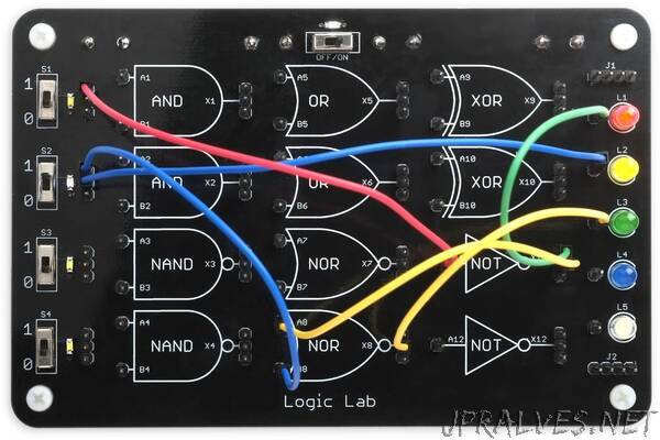
“The Logic Lab provides a selection of 12 logic gates that you can interconnect with patch cables to make a variety of different logic circuits, for experimenting with and learning about logic:
You can enter inputs using switches, and display the outputs on five coloured LEDs. The whole Logic Lab is implemented using a single AVR128DA48 (or ATmega4809) microprocessor and a few LEDs and other passive components.
I’ve included nine logic problems that you can try solving with the help of the Logic Lab.
Introduction
I originally decided to build this for a friend’s son who was interested in learning about logic gates, and I thought he would enjoy having something that he could use for practical experiments. I had a design in mind, and searched to see if anything similar already existed; the closest I found was a kit developed by the University of Southampton in the UK [1], but it wasn’t commercially available.
My first idea was to use 74LVC series logic gates, which are individual logic gates in small surface-mount packages. The nice thing about this is that each drawing of a logic gate on the PCB would be implemented by a single gate.
However, I then thought about using the Configurable Custom Logic (CCL) in the AVR DA-series microcontrollers, which allows you to configure three-input gates that work independently of the processor. The advantage would be that you could reconfigure the selection of gates in software, without needing to resolder the board. However, even the largest 64-pin devices only provide six logic gates, and in the 48-pin packages it seems that only five of these are actually available on I/O pins.
My final design used an ATmega4809 or AVR128DA48 microcontroller, but simulating the gates by polling the inputs, and setting the outputs accordingly, using truth tables stored in the program. With a 48-pin package it would be possible to emulate at least 12 gates of different types, which would be ample for the design I had in mind. This approach would allow you to change the selection of gates available by uploading a new version of the software, and then making stickers to show the new gate symbols.
Even though the logic gates are simulated using a microcontroller, the only detectable difference is the propagation delay. You can even create an oscillator by connecting the output of one of the inverters back to its input.
Description
The Logic Lab has the following features:
- 12 logic gates: two AND, two NAND, two OR, two NOR, two XOR, and two inverters.
- Four slider switches, S1 to S4, with LEDs to show the status, that can provide logic inputs to the gates.
- Five coloured LEDs, L1 to L5, that can display the state of the output from a logic circuit. The top three are red, orange, and green, allowing simulation of traffic lights.
- Two busses, J1 and J2, that can be used to link patch cables together.
- It is powered by two AAA batteries, with an on/off switch and power indicator LED.
- The inputs and outputs are connected to header pins, so you can interconnect them with a set of patch cables terminated in header sockets.”
