
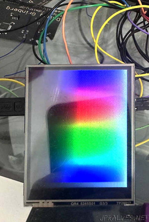
“I was searching for a display with at least 160x160 resolution and a resistive touch screen that would mate easily to RaspberryPi pico for my rePalm project. There were not many, actually. But I did come across this display at Waveshare - a 2.8inch 320x240 full-colour LCD. Without much further looking, I ordered a few and started planning the code to drive it. The goal was to have a framebuffer supporting 1, 2, and 4 bits per pixel greyscale, 8 bits per pixel indexed colour, and 16 bits per pixel full colour modes, while getting touch data in realtime. As this display does not support indexed colour or greyscale, that would need to be locally synthesized somehow. Additionally, I saw a few different articles out there about how people drive this display, and they were all atrociously inefficient, so I figured I could publish a way to do it right and save everyone else the trouble and pain. Presented here is a very fast driver for this display supporting 1, 2, and 4 bpp greyscale, 8-bit indexed colour, and 16-bit fullcolour modes on the whole display or any rectangular subset of it. Touch data is copied to a memory location for your perusal at your leisure automatically, and if you wish, you can even do tear-free page flipping and get VSync interrupts. No CPU cycles are used at all! A real, proper driver. So, why is driving this display properly a pain? Well…
The issues
Waveshare provides sample code for this device. It is beyond bad. The code assumes that you want to actively draw to the display - literally send pixels or rectangles of data to it manually, whenever you want to draw. I have no idea who’d actually do this sort of thing. It is pure insanity both in terms of code size and in terms of speed. The various articles I found from others on using this display did equally insane things, like DMA-ing a line of data at a time, and using the CPU to set up the next xfer. Oof… Luckily the datasheet for the LCD controller, the datasheet for the touch controller, and the schematic for this board are available. Now, normally you’d just set up a repeating DMA to the SPI controller to send the data to the screen repeatedly and call it done, but not this time. The idiotsjokers who designed this board apparently never considered that someone might want to actually use it. While there is a wide abundance of pins to use, they stuck the display, touch, and SD card all on the same SPI bus. They did provide some solder bridges that can be used to switch the SD card to its own bus, but the touch controller and the LCD are stuck sharing the bus. So, if I were to set up a repeating DMA to the screen, there would be no time to talk to the touch controller. I could use a timer to schedule the DMA, and do touch sampling, but that requires CPU involvement. I wanted a solution that used no CPU at all.
PIO
As I was using the RP2040, I decided to see if I could use PIO to solve this problem. Each PIO state machine is rather simple, containing only 2 general purpose registers, 2 shift registers, and space for at most 32 instructions (actually 32 are shared between groups of 4 state machines). They lack any ability to do math. The state machines can, however, send and receive interrupts, including from each other, and can send and receive data via DMA. I figured that with some effort I might be able to cobble together a working CPU-free driver for this display and touch screen.
Towards a solution
The math
First, some math. The stated maximum SPI clock frequency that this display controller chip supports is 62.5MHz. It takes 16 bits to send a single full-colour RGB565 pixel, and we have 320x240 of them. This means that the maximum possible framerate in the ideal conditions is 62.5e6/320/240/16 = 50.86fps. We’ll not reach this. In ideal conditions, sampling X, Y, and Z from the touch controller takes 51 cycles, and the maximum possible SPI clock rate when talking to the touch controller is 2.5MHz. This means that a complete X, Y, Z sample takes 51/2.5e6 = 20.4 microseconds. Since touch is noisy, it needs to be sampled rather often to provide enough samples for smoothing. I targetted 400Hz. So, per second touch sampling would steal 20.4400 = 8.16ms. With that removed, our new maximum possible frame rate for screen updating is (1-.00816)62.5e6/320/240/16 = 50.45fps. This accounts for 16bpp mode as well as the 8bpp indexed colour mode (since we’ll be sending it 16bpp data). For the greyscale modes, we’ll put the display into 12bpp mode to save on SPI traffic. For that, our maximum possible framerate will be (1-.00816)*62.5e6/320/240/12 = 67.26fps. Not bad. In theory… Now, we just need to sort out how to make it all work.
The 16bpp mode
The 16bpp mode is the simplest, since the display natively supports RGB565 fullcolour mode, so it made sense to start there. Things are pretty easy here. State machine 0 (SM0) here will ingest data, 16 bits at a time, and shift it out MSB first SPI-like to the display. But, remember, we need to sample touch. New plan. We set the X register to some value, say 2560. We then lower the display’s nCS, and send it data. We send pixels until we have sent X of them (this is approx 1/30 of a screen’s worth of pixels). After this we raise the display’s nCS and signal an irq to State machine 2 (SM2). We then wait for an irq back from it. SM2 was waiting all along. It lowers the touch controller’s nCS, gathers a sample, raises touch controler’s nCS, and signals an irq to SM0, which continues sending data to the screen. This should work and it does.
We’ll need some DMA channels to support this. Channel 0 will send raw screen data to SM0, when done, it will trigger channel 1, whose only job will be to re-start and re-trigger channel 0. Thus the display is constantly refreshing from our framebuffer. Touch is a bit more complex. To gather our samples we need to send three commands to the chip, and get three 12-bit responses. DMA channel 3 will program channel 2, in sequence, to first send the 3 commands to SM2’s TX buffer, then receive the 3 data points from SM2’s RX buffer, then reprogram channel 3 so that we can do this again in a loop. In actuality we’ll be receiving four data points, not three. More on why later. In any case, with these four DMA channels and two state machines, the 16 bit mode works. We get touch data DMAed to RAM and display image DMAed from RAM, all with no CPU involvement at all. Channel 2’s completion interrupt can be used to tell us when a new sample has arrived, if desired.”