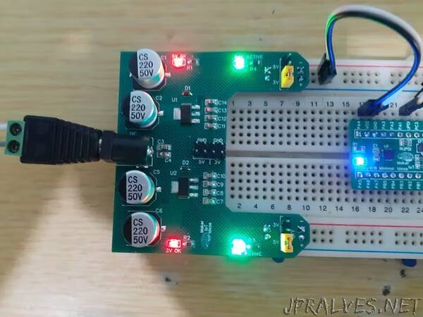
“My version of the breadboard power module. Optimised for what I need, without any unneeded components.
Breadboard Power modules are nothing new or exciting at all. I own a few commercial ones, and they are usually quite similar. They can be picked up for a few bucks and usually do what they are supposed to do, providing power to a project on a breadboard.
I decided to do my own version of one of these, as there were quite a few irritating flaws on all of the commercial versions that I have purchased over the years.
– They never fit my breadboard – This may seem strange, as I use a standard breadboard, but was never able to buy a power module that was a perfect fit.
– They contain unneeded components, like USB ports that take up a lot of space and a switch that all seem to fail in a very short time.
– The voltage regulators seem to all overheat, even at the minimum required input voltage
This got me to a point where I stopped using them at all, and started thinking about doing my own version. What I came up with, while not pretty, does exactly what I want it to, has decent smoothing capacitors on all power lines,
and does not overheat. I got rid of the switch, the bench power supply has a switch already, and also added LED status indicators for each rail, as well as the main DC power input.
The overheating problem was solved by giving the voltage regulators a big copper PCB heatsink each, which is many times the size of the actual regulator.That change, having used the same technique on many other PCBs before, immediately got rid of the heat issue, even at a 15v DC input, which is right at the maximum input voltage allowed.
The Custom designed Breadboard power module is however not perfect yet. on the cosmetic side, it is still not exactly symmetrical, with some weird irregular shapes on the PCB. This will be fixed in future, but for now, I am quite happy with its performance, which is actually all that I really care about.”
