
“Get rid of the breadboard while using your ESP-32S, and also reuse this for a small project that doesn’t need a custom PCB
The ESP32-S is, at least in my opinion, one of the most versatile microcontrollers available to the Maker at this moment. It ticks almost all of my boxes for features required in a microcontroller, with a lot of gpio’s, WiFi, and Bluetooth, as well as a lot of storage space for code. I do however have an issue with it, which I usually get around by designing a custom circuit board with a specific purpose. This is great for a project, but as most projects do not start on a custom-built circuit board, I am usually required to use a breadboard module. This is where my problems start. These modules are cumbersome to fit on a breadboard, to say the least, taking up a lot of space, and leaving very little space to connect to its pins with anything else.
Some of these modules do not even fit on the breadboard, making it necessary to hang one side off the breadboard or use two breadboards with a gap in the middle. I am quite sure many people can relate to this problem. My second issue is that when you have done your breadboarding, and want to go to a permanent project, which does not always need a dedicated PCB, you are now required to either live with things on a breadboard, scary to say the least or have a “spider” with many modules and wires, in a box or partly on protoboard etc…
My solution
You can get your own copy hereWhile not the most elegant, personally I really like the size, and layout of the humble Arduino Uno, with its standardised pinouts, and a large number of addon shields available for the platform. This made me think, sure, there are already ESP32-based boards in this form factor available commercially, but why not make my own instead, as well as a few of my most used modules in a standardised shield form, to make my life just that little bit easier?
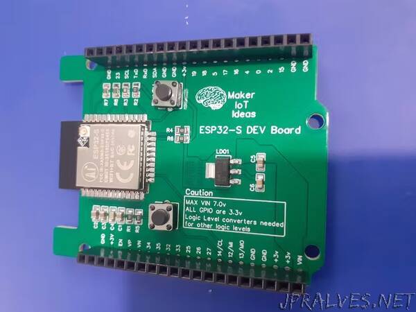
The picture above shows my attempt, with most of the GPIO broken out onto female header pins (except for the 6 gpio that are connected to the internal flash chip on the module).
The PCB explained…
Power:The board can be powered in two ways, either via the VIN pin ( at an optimal 7.0v DC – the LDO regulator can handle up to 15v, but I personally find that to stress it a bit hard ), which will use the onboard LDO voltage regulator to provide the needed 3.3v or from an external 3.3v PSU, which can provide a bit more current if needed…There are also plenty of 3.3v and ground connections on the two 20-way headers to connect to other sensors. Strapping PinsAll the required strapping pins are pulled up or pulled down, as per the datasheet, to 3.3v or ground respectively. GPIO PinsAll GPIO pins are clearly labelled on the silkscreen to make it easier to use.I did however not stick to the Arduino labelling convention, as I don’t always use the Arduino IDE, and the actual GPIO numbers are in my view, more useful then. Flashing code to the boardIt will be quite obvious that I did not include any USB-to-serial converter on the board, the reason for this being that, in my opinion, 1) it wastes space on the board2) it is not actually necessary, as we can upload with an external uart adapter, or use OTA ( which I actually do most of the time )3) In an actual project, that USB port is going to attract problems, especially if you give it to someone else to use…”