
“A simple project, making a vibrational sensor module which can be used with microcontroller digitally and brief theory behind op-amps
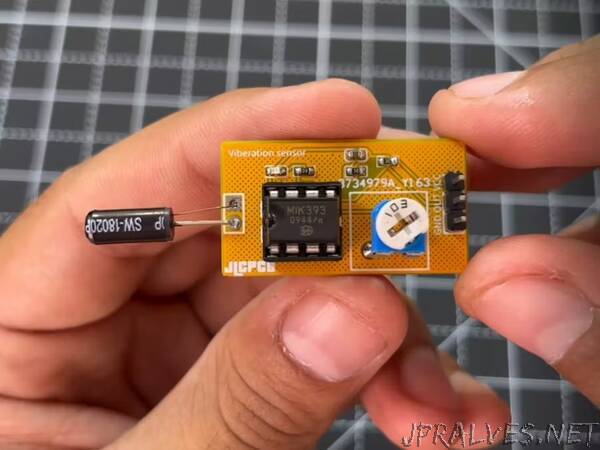
Recently, I got a vibration sensor from one of my friend, which is highly sensitive to vibrations and I want to convert this into a fully fledge vibration sensor module. The sensor is SW-18010P has two wire interface. This one is also known for waterproof action, shock spring switch. We will use this sensor with operational amplifier to get a digital output.
SW-18010P sensor:
This sensor has a spring inside, not any type of directional/ angle vibrations. Sensor can be triggered using a simple hit on the outer cover of the sensor. The switch is open circuit (off state) when it is static and has a 10Mega ohm open circuit resistance. Internal connections (metal surface) touch with each other to turn on the sensor.
The switch become close and possess a small 5-ohm resistance which allows 20mA of max current. SW- sensors comes in a lot of packages which can be seen all over the internet. Some of them have high sensitivity or some are made for high power ratings.
Operational amplifier as a comparator:
We are using concept of the comparator, so it is must to know about this configuration of operational amplifier. basically, it is the open loop configuration of the op-amp which is used to provide the logical output according to the input. The input signal is get compared, we can set the reference using a 10k potentiometer which then used to set the sensitivity.
Here in this project, we are using non inverting comparator, the signal is given to non-inverting terminal and inverting terminal is free to set the reference accordingly. See more details about different configuration from here.
Components required:
- Lm393 Operational amplifier
- SW-18010P Vibration sensor
- 5v battery
- Small SMD led
- 10k, 1k resistor
- 100nf capacitor
- 10k potentiometer”