
“When I was a kid, there were several political murders in the ex-YU that involved people who had Surveillance Systems that mysteriously stopped recording during the event and resumed without an issue immediately afterward. Weird right? With no evidence of tampering with the data ie. deleting recorded videos, the only explanation was that the power to the system was cut for a brief moment - resetting the system and inducing a long boot sequence, long enough for the pre-planned operation to be performed. The other explanation was that the “authorities” simply lied about the lack of evidence…
In any case, having a device that would alert you when the power is lost in your home, or on a specific phase, would definitely be useful – even for the people not living in one of the ex-YU countries. I once forgot that the ground of my Oscilloscope wasn’t isolated and attempted to measure AC Mains voltage. My probe melted, and the Scope seemingly died. Lights and appliances in my home remained on, and in the panic that ensued it never occurred to me that the breaker on the particular phase the Scope was connected to could’ve popped – not the Scope itself. After an embarrassing phone call about a warranty, and the realization that breakers are a thing, I just lifted the one that popped and the Scope came back to life.
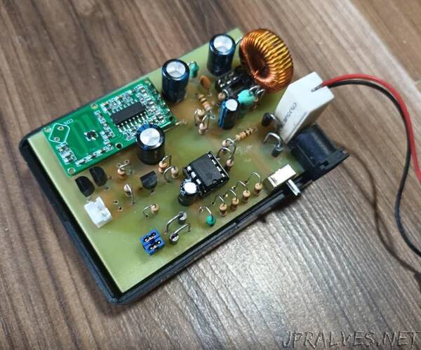
Here’s a project I did over the weekend - an alarm system that gets triggered whenever the power is cut, or when presence is detected within a 7-meter radius of where it’s placed. It is a 100% Analog project that’s easy and cheap to make, even by people who don’t understand what’s going on in the circuit.
I did something similar a few years back, when I didn’t have a firm grasp on Circuit Theory, with the PIC10F200 and an extremely poorly designed Audio Power amplifier that was hooked to a 5W Speaker. Circuit was made using those cheap blue modules from China - Battery Charger (TP4056) module without protection, and Boost Converter (MT3608) module for powering the RCWL-0516 sensor. It had many problems and you shouldn’t try to make it, one of them was high Quiescent Current of the Audio Amplifier that discharged the battery within 30 minutes – even faster if the Alarm got triggered while the power was off. Looks good on the first glance, right? It’s not.
This version can run for up to two months on a single 9V Zinc-Carbon battery – double if you are willing to pay 4$ for an Alkaline variant – not me. If the alarm gets triggered, and remains triggered indefinitely, the device can remain active between 10-20 hours all while producing a nice 90dB ear-piercing screetch - assuming that you are boosting 9V input voltage to 24V, and using the cheapest/lossy components.
In this particular circuit, I am using a 28V active buzzer that draws 15mA when conducting. Efficiency can be greatly improved by using low-ESR capacitors, choosing a better inductor, and most importantly lowering the boosted voltage. If you can find a sufficiently loud active Buzzer rated at lower voltage ex. 12V, you only need to change the feedback resistors and your efficiency should drastically improve - but is it worth the additional effort? That depends on how often you expect the device to trigger while the electricity is cut. If you live in a country that has a stable electrical grid, or you don’t mind spending cca. 2$ on a 9V battery now and again, you probably shouldn’t bother.
N/C Parts
You may have noticed some N/C components in the circuit. They have been placed just in case something needed to be tweaked after the board has been made.
R16 - If omitted, Power Trigger will be delayed for a few seconds after the electricity is cut - duration depends on the type of a Wall Wart you are using and it’s output capacitance. The lower the value, the faster the triggering is.
R15 - Some Buzzers may may require a resistor placed in parallel to work.
R14 - Optional pull-down resistor to prevent the D-Pair from conducting when it shouldn’t.
Making the board by hand is probably going to be the most challenging task, luckily it can be ordered for as low as 2$ from some Chinese manufacturers if you don’t mind the wait time that can vary between a week to a month.
General
This probably shouldn’t be mentioned, but you need the following:
- Soldering Iron
- Solder Wire
- Desoldering Whick (Optional)
- PCB
To make the PCB using the Toner Transfer method at home:
- Laser Printer - The PCB layout must be printed using a Laser Printer for it to be transferred successfully to a copper-clad board.
- Magazine \w Glossy Paper - Glossy magazine paper is ideal for transferring the printed layout. You can try using the regular one, but the quality of the transfer will be crap at best.
- Copper Clad Board - They are fairly cheap and can be found for as low as 15 cents. One single-layer board that can be cut down to cca. 80x55 millimeters is required for the project.
- Saw - For cutting the board to the required size. If you don’t care about the “neatness” of your build, just transfer the print on a generic 100x70mm board and call it a day.
- Sand Paper - It is extremely important to remove the layer of oxidation from a copper-clad board before attempting the transfer. Even if your board looks “pristine” - it probably isn’t.
- Acetone - You can use nail polish remover as an alternative, but I recommend Acetone of 90% or higher purity. It is required for cleaning the copper-clad board and removing the toner.
- Ferric-Chloride - Common etchant used for making PCBs. A liter of the high-quality one can be found for as low as 10$ and it will probably last you for several years.
- Clothing Iron or Modded Laminator - Heat is required for transferring the printed layout to a copper-clad board. Clothing Irons or Modded Laminators are commonly used for the task.
- Drill - 0.8mm drill is needed for making holes in the board for THT components.
Note: You would ideally want to make a DIY PCB for a project like this to improve its reliability, robustness and reduce its size – but you can make it on a perfboard with copper pads just as well – although I wouldn’t recommend it because of the Boost Converter. It’s a low-frequency one (MP34063) so it may work, but how well I don’t know.
Components
Except for the RCWL module, all components presented in the following list should be readily available to you - they are dirt cheap and can be sourced from any local electronic store for less than 5-cent each. One thing that you should keep in mind is that capacitors MUST be rated at 25V or higher, and resistors MUST be able to handle at-least 1/4W. If some component isn’t available, KiCAD project is provided so you can alter the layout accordingly.
1x DC Jack
2x JST PH Connectors (Male)
1x 9V Battery
1x 9V Battery Connector Cable
4x 1N4007 Rectifier Diode
1x 1N5817 Schotky Diode
1x Slide Switch
2x 10uH Choke
1x 100uH Inductor
1x 100pF Ceramic Capacitor
2x 10uF Electrolytic Capacitor
3x 100uF Electrolytic Capacitor
1x 0.4 Resistor
1x 100 Resistor
1x 220 Resistor
1x 560 Resistor
1x 1k Resistor
1x 4.7k Resistor
7x 10k Resistor
2x 27k Resistor
1x 47k Resistor
2x 100k Resistor
1x Male Header (2x2, 2.54mm)
3x 2N3904 BJTs
1x MC34063 IC
1x LM393 IC
1x RCWL-0516 Module
1x 28V Buzzer”