
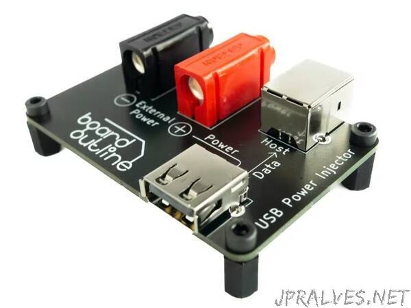
“The USB Power Injector allows a convenient way to power up USB 2.0 devices from a lab power supply, while still allowing data transfer.
When powering devices from a standard USB 2.0 port, either from a PC or from a standard USB hub, you never have the niceties that an adjustable lab style power supply has. During development that means you can’t set precise voltage and current limits. In the best case scenario, that means you can’t test under/over voltage protections. In the worst case, you run excessive current trough your device and you don’t even know that’s happened.USB hubs tend to have overcurrent protection, but most don’t send the overcurrent event to the operating system.That can cause confusion and loss of time for a hardware engineer during development or to testing personnel during production.This project allows a way to conveniently power a USB2.0 device from a lab power supply and thus avoiding the problems described above.
The schematic for this project is quite simple.
There are two USB connectors. USB A - for a connection to the device under test and USB B - for a connection to the host. The two USB connectors are connected with a differential pair as denoted by D_P and D_N.
The USB A connector gets its power from the two 4mm banana jacks - one black and one red, in order to denote polarity. This allows the device under test to be powered from an external lab power supply with just 2 standard banana to cables, like the once showed in the photo.
The layout is equally simple. In order to route the USB traces at 90ohms impedance, the JLC7628 stack up was used. The traces were routed with a spacing of 0.127mm and width 0.2mm, as per JLC’s impedance calculator. Layers 2 and 3 are ground plains.Yes, this board work just fine as a 2 layer board, since the traces are short, but 4 layer boars are cheap and I wanted to get the required 90ohms impedance, as specified in the USB2.0 standard.
I designed the silk screen to be as descriptive as possible for anyone using the board. It describes both the power path and the data path.”