
“Abstract
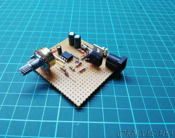
This project is about, controlling a fan using 555IC with PWM. PWM is controlled with a potentiometer. I drove a fan but you can use it for a DC motor. The circuit has a back-emf diode. I did this project using a prototyping board but if you want to produce the PCB, I will share the Gerber files too.
Features
- Input has a 500mA fuse for protection.
- PWM is controlled with a 10k potentiometer
- Min. duty-cycle limiting at %25
- 1.5kHz PWM frequency.
- 1A@12V input supply.
- On/Off Switch.
- Back-emf diode for the motor.
- 350mA max @ 12V fan.
I selected these features but you can change input power, minimum duty-cycle value, or frequency depending on your motor power. I will show you later.
Circuit Material List
1xTLC555
1xIRF3710ZPBF
1x12V Fan
1x500mA fuse
1xOn/Off switch
1xDC Power Jack
4xSchottky or Standard Silicon Diodes
2x2.2uF, 1x1uF, 2x100nF, 1x10nF capacitors
1x10k Pot
1x3.3kOhm, 1x2kOhm, 1x1.2kOhm resistors
At least 5x5cm Prototyping board
Any adaptor plug above 500mA @12V
Mechanic Material List
If you want to make a box too, I will share the STL files.
Circuit protection box
Some support materials for holding the fan
2 sides tape
Some screws and nuts
As you can see in the photos above, a flexible, I guess aluminum material holds the fan. I found it in an old desk lamp.”