
“Creating a simple oscilloscope with the Basys3 board
Introduction
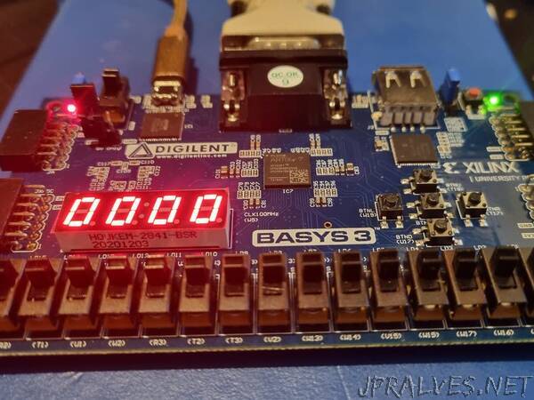
The Digilent Basys3 board is a very capable board to get started developing FPGA projects with. It provides the users with an Artix 35T device, USB-UART, Four Pmods - Including one configured for the XADC, 12 bit VGA and switches, LED and Seven Segment Display.
This project is designed to demonstrate just how capable the Basys3 board is, to do that we are going to create a simple oscilloscope which can use the XDAC Pmod input channels and the VGA display to display the waveform.
To do this we are going to use a MicroBlaze controller to run the application and control the measurement of the XADC and determine where to plot the data on the VGA screen.
The VGA Display will be 640 by 480, 12 bit RGB to render this in software memory would require 3, 686, 400 bits. This exceeds the 1, 800, 000 bits of BRAM available in the FPGA. The processor is unable also to run at the speed necessary to be able to achieve the required frame rate.
We will get around this issue by using the processor to determine the data point plots, while the logic renders the frame for display in real time. To do this we are going to be using a High Level Synthesis Core which we create first.
High Level Synthesis Core
To get started was re going to create a HLS core which can plot up to 10 samples in the VGA display (you can of course change this later). The HLS core will generate a AXI Stream which is 640 pixels by 480 lines. To update the display on each frame there will be sample_x / _y registers which define the location of the sample data, a register to define the size of the data point, and a final register to define the data point color.
Creating HLS streams requires a simple definition using the ap_fixed.h and hls_video.h libraries.
We will have a 32 bit pixel, which includes 8 bits for each RGB but also a 8 bit alpha channel for blending.”