
“A UV Exposure Box to expose photoresist or solder masks for single and double boards.
Most of the projects that I build have a custom printed circuit board. With a preference to making my own PCBs rather than use proto-boards, the minimum track width is usually limited by the method used to make the board. With the Toner method, minimum track width is about 0.016in. To get smaller tracks than this, photographic methods are better suited.
There are a number of tutorials on how to create a board using the photoresist method so I won’t cover it here. See DIY PCB Using Liquid Photoresist for one such method.
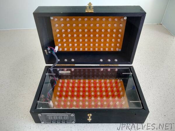
This project is about creating a UV exposure box to cure the photoresist. I based my design on the LED UV exposure box by Electrobob. The box was built from 40mm x 9mm dressed pine with the top and bottom covered with 3mm MDF. The hinges and clasp was purchased from a local hardware store. The dimensions of the final box is 233mm x 140mm x 86mm.
The circuit
The timer is built around the ATtiny1614 microprocessor. The 4-Digit 7-Segment display is driven by a MAX7219 LED driver. The four switches are connected to a voltage divider which is read by the microprocessor as a analog value. The UV LED lights are switched on via a relay.”