
“Using an ATtiny1614 processor with LiPo battery, including USB charging circuitry and logic. It is programmable with Arduino IDE!
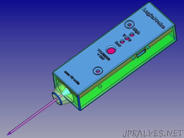
I would introduce to you this Logic Probe, a complete instrument. It is simple but effective to measure digital logic levels 0 (zero) and 1 (one), both TTL and CMOS technology; the maximum accepted level is 10 volts but CMOS can reach up to 18 volts you would avoid. To use it just connect the Mini USB wire with black ‘crocodile’ clamp to the GND of your circuit and touch the probe where you want to know the logical level (in the same circuit) and look at the corresponding LED that will light up.
Usually with Arduino and similar processors as ATtiny used in this project, we find TTL at 3.3v and 5.0v where the ‘zero’ and ‘one’ logical levels are the same: from 0.0 to 0.8v is considered as 0 (LOW) and from 2.0 to 3.3 up to 5.0v is considered as 1 (HIGH); between 0.8 and 2.0 is considered UNDEFINED.
On of the three LEDs will light up at each corresponding level:
TTL levels, both 3.3 and 5.0 volts:
low=blue <= 0.8v
high=red > 2.0v
undefined=yellow >0.8v <= 2.0v
CMOS levels, up to 18 volts (here the limit is 10 volts):
low=blue <= 1.5v
high=red > 3.5v
undefined=yellow >1.5v <= 3.5v
Components List (MPU small board):
- MPU ATtiny 1614 SMD
- Mini USB female PCB SMD connector
- 2 x SMD capacitors 100nF
- SMD Resistor 270 Ohm
- SMD red LED
- SMD 662k voltage regulator to 3.3v
- 16 x strip line thin pins 0.6mm diameter
- Double faced SMD PCB
Components List (main board):
- Sliding switch on/off
- 6 x 10k Ohm 1/4W Resistors 1%
- 5k6 Ohm 1/4W Resistor
- 22 Ohm 1/4W Resistor
- 5k Ohm 1/4W Resistor 1%
- 3 x 150 Ohm Resistor
- 15 Ohm 1W Resistor
- BC337 NPN Transistor
- Axicom SMD 3.0v Relay
- 1N4148 Diod
- Ceramic Capacitor 100nF
- Push Button normally open
- Red LED 5mm
- Blue LED 5mm
- Yellow LED 5mm
- 300mA/h 3.7v 1s Lipo Battery
- Small Plastic box (see 3D project below)
- Metal Probe
- around 20 copper 0.6 small rivets (for pass through holes)
- Double faced PCB
- 3 x strip line pins for the Switch
- 2 x strip line 90° pins for the Battery
- 2 x Screws 3mm and supports
- ‘Crocodile’ black Clamp, 40cm of black wire and a Mini USB male connector”