
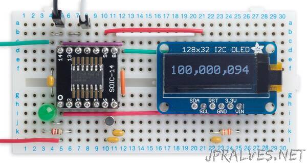
“This project is a simple frequency meter capable of measuring frequencies up to 100MHz with an accuracy of 0.002%. Based on an ATtiny414, it demonstrates the use of Timer/Counter TCD0 and the Event System
I recently wanted to design a frequency meter that would measure up to 100MHz, so you can use it to test processor clocks and crystals. There are many designs for microcontroller-based frequency meters on the web; after all, it’s one of the applications that the timer/counters in most microcontrollers are designed for. However, most of them don’t go as high as 100MHz because the microcontroller’s own clock usually imposes an upper limit of half the clock frequency.
First attempt
My plan was to use the Real-Time Clock peripheral, clocked by a 32.768kHz crystal, to generate a 1Hz interrupt. A second timer/counter, clocked by the frequency being measured, would then count the number of cycles in this one-second interval. The result would simply be the frequency, in Hz.
For my first prototype I used Timer/Counter TCB0 clocked from an input pin, with the capture triggered by the 1Hz from the Real-Time Clock peripheral. I confirmed that I could only measure up to half the clock frequency, or 10MHz, so I’d need a four stage prescaler to divide the 100MHz input frequency by 16 to bring it within the range I could measure. This led to me experimenting with using the CCL as a prescaler, which I wrote about in the earlier article Frequency Divider Using CCL.
Using Timer/Counter TCD0
Just on the off-chance I thought about trying Timer/Counter TCD0. This is a 12-bit device, but unlike most other timer/counters it’s asynchronous; in other words, it works independently of the processor clock.
TCD0 is primarily designed for waveform generation in applications such as motor control, and I don’t pretend to understand most of its features, but it seemed that it should be possible to get it to capture the counter value under control from the Real-Time Clock.
It turned out that I could clock TCD0 at well over 100MHz, which would allow me to design this really simple frequency meter with the range I was looking for, without needing a prescaler.
Using the Event System
I could have used the Real-Time Clock to generate an interrupt every second, and then capture the count from Timer/Counter TCD0 in the interrupt service routine. However, the recent AVR processors provide an Event System which provides a better way of doing this. You can generate an internal signal from the Real-Time Clock, and use this to trigger the capture directly. The advantage is that there’s none of the overhead of calling an interrupt service routine, so the response is virtually instantaneous.
Choice of microcontroller
Microchip now have three new ranges of AVR microcontrollers: the ATtiny 0-, 1-, and 2-series, the ATmega 0-series, and the AVR DA- and DB-series. They all have similar peripherals, so I could have chosen, for example, the ATtiny414, ATmega4809, or AVR128DA28, all of which can use an external 32.768kHz crystal for timing, and which include timer/counter TCD0. I tested a first version of the circuit with an AVR128DA28, but for the final version I chose the ATtiny414 because it has a more compact package, and I didn’t need the extra I/O lines.
I had the events working with the AVR128DA28, but then after switching to the ATtiny414 they no longer seemed to work, and the problem turned out to be the different terminology used on the earlier processors. I’m grateful to user kabasan on AVR Freaks for helping me out. If you want to learn about using the Event System I recommend starting with the AVR DA- or DB-series, which have more logical terminology.
Note, don’t confuse the ATtiny 1-series ATtiny414, released in 2020, with the older ATtiny441 which was released in 2014 as an enhanced version of the older ATtiny44.”