
“Neon lamps, also known as neon glow lamps, are wonderful little bulbs that glow orange when you give them high voltage and low current. Neon lamps are mostly obsolete now; they belong to an era when many electronic devices were supplied with high voltages in order to drive vacuum tubes, and the voltages required for neon lamps were convenient and accessible. Compared to an LED which might have a voltage drop of 3V, a neon lamp’s striking voltage on the order of 100V makes it impractical for use in modern circuits, which use transistors instead of vacuum tubes and require much lower voltages.
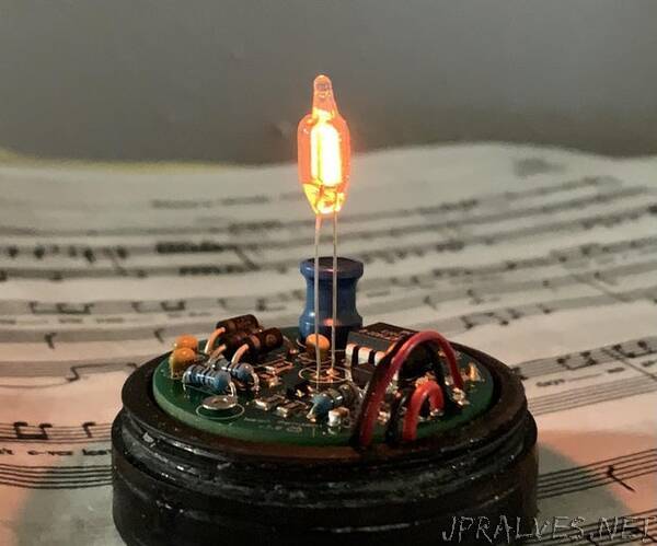
However, neon lamps look really cute! They deserve better than to be consigned to the history books, thrown out in favor of surface-mount LED’s lacking any sense of personality. With this in mind, I decided to create a small, portable neon bulb light. I wanted my creation to have these properties:
Small (as small as possible)
Long battery life (1 day at least)
Wirelessly rechargeable (compatible with any phone charging pad)
Since I wanted to minimize the size of my circuit, I chose to create my first printed circuit board, using Autodesk Eagle. Initially I wanted to make a necklace with a glowing neon lamp, but the size of the charging coil and the height of the inductor on the PCB made that difficult, so it morphed into a tea light. Maybe I’ll try to make an even smaller version in the future!
This project requires medium difficulty electronics (regular soldering, surface-mount soldering with solder paste) and medium difficulty hardware (3D printing, sanding/filing). If you want to skip the theory and jump straight to building it, skip to Step 7: Order the PCB!!!. Also, it may take a lot of experimentation to get the wireless charging to work reliably, because the battery is placed so close to the charging coil that it can absorb a good portion of the energy transmitted by the charging pad. A couple tips to deal with this are detailed in Step 14: Troubleshooting.
Let’s get to it!
Supplies:
Tools:
Soldering iron and solder
Multimeter and alligator clips
3D printer (I used a QIDI TECH Shadow 5.5S resin printer, you might have some difficulty with the 3D printed threads on the case if you use an FDM printer)
Wire cutters
Tweezers
Surface-mount solder paste (https://www.digikey.com/en/products/detail/chip-quik-inc/SMD291AX10T5/3972568)
Heating pad for SMD soldering (I used this cheap one)
Wireless Charging Pad (like this)
Parts:
I strongly recommend ordering this SMD component assortment, since it has nearly all the surface-mount parts you need for this project.
Through-hole Components:
1x 1.5M 1/4W resistor
1x 18k 1/4W resistor
1x 8.2k 1/4W resistor
3x 100nF 100V ceramic capacitors
3x MUR120 switching diodes 200V
1x 150uH 1A fixed inductor
1x LT1073 DC/DC converter chip
1x NE-2 Neon Glow Lamp
Surface-mount Components:
1206 package resistors:
2x 10M
4x 100k
1x 220
1x 33k
1x 4.7k
1x 470 resistor (0603 package)
2x 4.7uF capacitors (0805 package)
1x 1N4001 diode (SMA package)
1x Red surface-mount LED (0603 package)
1x 2N3906 pnp transistor (SOT23 package)
1x MCP73831 LiPo charge controller
Miscellaneous Parts:
1x 3.7V 502030 LiPo battery
1x Qi Wireless Charging Receiver
2x M2 screws, 12mm length
2x brass M2 screw inserts, 6mm x 3.5mm
You’ll also need to order a custom printed circuit board for this project.”