
“Drive without distracting your sight, take care of speed limits, “fucking” speed traps taking under control your car speed on windscreen!
Software point of view:
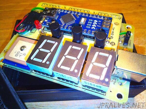
Projecting the circuit the most difficult and confusing part have been the connection of the displays 7 segments to the BCD decoders because number are “inverted”, mirrored.
There are 3 buttons: + and - for increasing/decreasing brightness and S/H to switch between Speed and Heading; in case of heading also the red LED is on, it means “degrees” of compass (1-360°). The brightness is saved in EEPROM memory after a minute. Brightness is changed both on displays and on LED by the way of PWM pins.
An important part of the code is for collecting datas from GPS, mainly speed and direction, taking them out from every NMEA sentence. Even using String class, mostly for Serial NMEA sentences manipulation, the whole elaboration flow is stable and solid; it uses “serialEvent()” to receive data from GPS one time per second, than calls “nmeaExtractData()” and finally it checks data packet with “nmea0183_checksum() to be sure of data integrity. If you use another make and model GPS be sure the sentences have the same structure or you have to make some changes here. For example EM406A uses “$GPRMC” packet id, BT220 uses “$GNRMC” instead… just a small name change… A useful link can help you with checksum test: https://nmeachecksum.eqth.net - Here an example of a complete NMEA sentence, it contains: id, time, validity, latitude, longitude, speed, true course, date, variation and checksum.
$GPRMC, 095836.000, A, 4551.9676, N, 01328.7118, E, 2.09, 341.84, 280519,, *08
The sketch provide to enable the latch for every single display BCD decoder, set the code number on the binary 4 bits bus, disable the latch, and so on when value changes. Left side not significant zeros are blanked.
Before loading a new sketch remember to take out the Jumper: it is connected to Rx pin of Arduino and during loading it can be in conflict with GPS Tx. After software loading put again in place the Jumper to restore normal functionality.
Components list:
1 x MPU Arduino Nano
3 x 5161as seven segments displays, common cathode, red
1 x Beitian BN-220 serial TTL GPS (1 Hz GPRMC sentences)
1 x Jumper
3 x buttons (normally open) + 3 x caps
22 x 1/4W 220 ohm resistors
1 x 3mm LED, red
2 x 100n capacitors
3 x 14511 BCD decoder + latch
1 x USB “B” female
1 x strip line 2x male pins (for Jumper)
1 x strip line 4x male pins (for GPS)
1 x pigtail cable connecting GPS to 4 pins onboard
22 x strip line male pins to join two PCB in a stack
1 x piece of double sided adhesive to stick GPS on PCB
6 x turned strip line 5x female pins (for Displays)
50 x copper 0.6mm rivets
8 x M3 screws
4 x M3 female towers 20mm high
1 x plastic box + cover (look at my 3D files ready to print below)”