
“Binary displays are very popular for clocks so it looked like there a gap waiting to be filled in the measurement area with an instrument that displayed its results in a Binary format. As result I decided that a DVM would be a suitable project to be given a Binary makeover.
The Microbit has the means via an ADC (Analogue to Digital Converter), to convert analogue inputs into digital values. These digital values can then be used to create a myriad of applications.
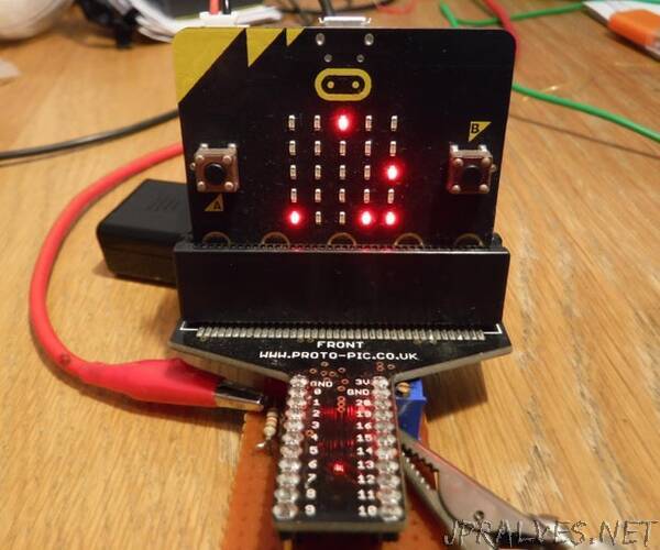
In this case I will describing how to make a Battery powered Digital Volt Meter (DVM), but in addition to this I will have the ability to display the voltage in Binary as well as the usual Decimal values.
** NOTE ** ENSURE THAT ANY VOLTAGE DIRECTLY APPLIED TO THE MICROBIT DOES NOT EXCEED THE SUPPLY RAIL (~3V), AS YOU WILL DAMAGE THE MICROBIT
If you were to apply a DC input to the ADC this being limited by the supply would mean that ~3V would be the maximum.
However, there is a way to overcome this limitation with a few additional components to measure voltages greater than the supply without causing damage to the MicroBit.
It must be noted that there is a limitation to what this simple DVM will measure and its only intended for low voltage positive DC applications in this case 0 to 20V.
Supplies:
MicroBit - Qty 1
Battery Pack - Qty 1
9k resistor - Qty 1_
_953R resistor - Qty 1
200R multi turn potentiometer - Qty 1_
_1K resistor - Qty 4
*All resistors 0.1W or greater.
Veroboard - Qty 1
Veropins - Qty 3
Bread:bit Edge Connector Breakout Board - Qty 1 or similar to allow the Microbit to be connected to the potential divider.
LED red low current - Qty 2
16 pin DIL socket or SIL socket strip - Qty 1
DMM
PSU, fixed or variable voltage.
PP3, 9V non rechargeable battery.
In the absence of a PSU a battery as indicated may be substituted.
4 pin single in line (SIP), pin header - Qty 2”