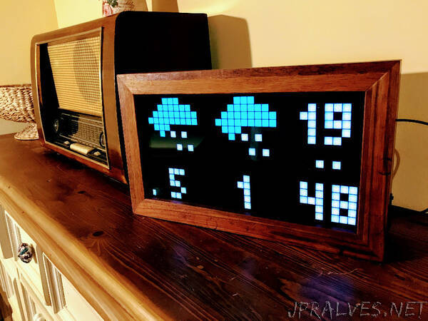
“This driver controls Chinese RGB LED Matrix modules without any additional components whatsoever.
Display structure
The display basically consists of 6 large shift register. On the input connector you will find the inputs to the shift register (two for each color - Rx,Gx,Bx), a 2 to 5 bit latch address input (A,B,C,D,E), a latch enable input (LAT/STB), a clock input (CLK) and the output enable input (OE).
There are a few basic row scanning layouts: 1/4, 1/8, 1/16 and 1/32 row scan. You can enable the correct pattern for your display with display.begin(n) where n={4,8,16,32} defines the pattern.
For example, the 32x16 displays work like this (other varieties operate accordingly): Each of the shift register is 64(1/4 row scan) / 32(1/8 row scan) bits long. R1 and R2 will together therefore cover 128(1/4 row scan) / 64(1/8 row scan) bits or 4(1/4 row scan) / 2(1/8 row scan) lines respectively. The rows are, however, not next to each other but have a spacing of 4(1/4 row scan) / 8(1/8 row scan). In case of 1/4 the row scan pattern may also alternate between rows or even reverse bit order.
Such LED matrix are usually used as a sub-module for larger displays and therefore feature an output connector for daisy chaining. On the output connector you will find the identical signals to the input connector where A,B,C,LAT,CLK are simply routed through and (R,G,B) pins are the outputs of the shift registers on the module.”
