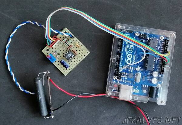
“The current measurement requires the use of an ammeter placed in series with the load. An ideal ammeter has no voltage drop, i.e. it is a short circuit. But most of the current sensors are based precisely on the measurement of the voltage drop on a resistor which, according to Ohm’s law, is proportional to the current that passes through it.
For what has been said, a good real ammeter must have a very small voltage drop, this in order not to alter the circuit under measurement with its insertion. The sensor I present has a voltage drop of only 50 mV and uses easily available components.
The shunt
The most accurate system is to use a shunt, i.e. a resistor with very low resistance compared to that of the load and the generator. Of course today we also find on the market sensors based on the Hall effect, that is a device that measures the magnetic field generated by the current passing through a wire for the well-known Ampere’s law, but these semiconductor sensors do not have comparable stability and precision. Figure 1 shows the typical appearance of a 10A and 75mV shunt.”
