
“Last summer on vacation in Maine we met a very nice couple. The wife was blind and had been blind since the birth of (I think) their first child. They were a really nice couple and we had a lot of laughs together.
After we came home, I couldn’t stop thinking about what it would be like to be blind. The blind have seeing eye dogs and canes and I am sure a lot of other things to help them. But still, there must be a lot of challenges. I tried to imagine what it would be like and I wondered, as an electronics nerd, if there was something I could do.
I burned my eyes one summer with a welder when I was around 20 years old (long story…dumb kid). It’s something I’ll never forget. Anyway, I had my eyes patched for a day. I remember my mother trying to walk me across the street. I kept asking her if the cars had stopped. She said something like, “I’m your mother…do you think I’d walk you out into traffic?” Thinking back on what a dweeb I was when I was a teenager, I wondered. But I couldn’t get over not knowing if there was something about to hit me in the face as I walked. I was very happy and relieved when we took the patches off. That’s the only thing close to ‘experience’ that I have had in my life with regards to blindness.
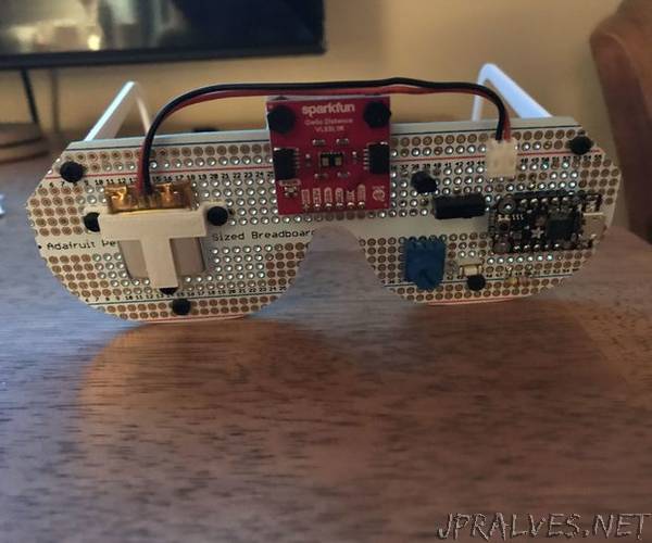
I recently wrote another Instructable about a young friend at work who lost his sight in his right eye and a device I made for him to tell him if there was something on his right side. If you want to read it it’s here. That device used a Time-of-Flight sensor by ST Electronics. About a minute after finishing that project I decided that I could make a device to help the blind. The VL53L0X sensor I used on that project has a big brother/sister sensor called the VL53L1X. This device can measure greater distances than the VL53L0X. There was a breakout board for the VL53L0X from Adafruit and for the VL53L1X there was a breakout board from Sparkfun. I decided to create a pair of glasses with the VL53L1X on the front and a haptic feedback device (vibrating motor) behind the glasses near the bridge of the nose. I would vibrate the motor inversely proportional to the distance to an object i.e the closer an object was to the glasses, the more it would vibrate.
I should note here that the VL53L1X has a very narrow Field of View (programmable between 15-27 degrees) meaning, they are VERY directional. This is important as it gives good resolution. The idea is that the user can move their head like a radar antenna. This along with the narrow FOV allows the user to better discern objects at different distances.
A note about the VL53L0X and VL53L1X sensors: they are time-of-flight sensors. This means that they send out a LASER pulse (low power and in the Infrared spectrum so they are safe). The sensor times how long it takes to see the reflected pulse come back. So distance equals rate X time as we all remember from math/science classes right? So, divide the time in half and multiply by the speed of light and you get distance. But as was pointed out by another Instructables member, the glasses could have been called LiDAR Glasses as using a LASER in this way is Light Distance and Ranging (LiDAR). But as I said, not everyone knows what LiDAR is but I think most people know RADAR. And while infrared light and radio are all part of the electromagnetic spectrum, light is not considered a radio wave as microwave frequencies are. So, I’ll leave the title as RADAR but now, you understand.
This project uses basically the same schematic as the one for the other project…as we’ll see. The big questions for this project are, how do we mount the electronics on glasses and, what kind of glasses do we use?”