
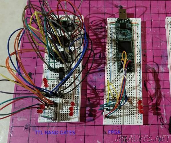
“Designing hardware logic circuits can be fun. The old school way to do this was with NAND gates, on a bread board, wired up with jumper wires. This is still possible, but it doesn’t take much before the number of gates gets out of hand. A newer option is to use an FPGA (Field Programmable Gate Array). These chips can rewire themselves to become any digital logic circuit you can design, but aren’t cheap and readily available. I will show how this FPGA can be replaced with a cheap Atmega chip from an Arduino UNO, effectively putting the digital circuit into a DIP package, which is very breadboard friendly.”