
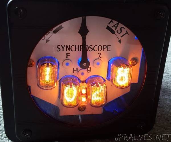
“I wanted to build a Nixie clock driven by an Arduino and found a few places on the internet, but none were 100% complete to get it working from the beginning to end. I either found bad wiring diagrams, bad code in programs or bad supporting literature that really slowed down my progress, so I gutted it out, figured it out and came up with the following. Maybe someone can say well, you missed this or that… Hopefully i haven’t and I have given you enough here to let you find the mistakes. Anyway… this is my Nixie clock / Weather station. I used a Syncroscope from a Nuclear power plant for the case. The clock displays the time from the top of the minute to 15 sec in, and then displays the temperature (F), then back to time until the bottom of the minute (30 sec.), then it displays atmospheric pressure (mm Hg), then back to time until 45 sec into the minute and displays relative humidity. Upon reaching 60 sec. it increments the time and repeats the cycle. The BMP280 has a very poor temperature sensing capability and is not nearly as accurate as a DS18B20 Waterproof Temperature Sensor that I used in another project of mine. I may just swap this out. Also I had a nice mesh cage around the sensors to protect them from damage and this too led to inaccurate results so I modified that as well. The indicator arrow is scaled for the low and highest pressures found in my state. the indicator arrow does a good job of showing changes in the pressure when a storm or clear skies are developing.
Materials:
Arduino Mega - For the Output count.
Real Time Clock Module - DS3231 AT24C32 IIC precision Real time clock RTC memory module
Pushbutton Board -
Micro Servo -SG90 Mini Micro Servo
DHT22 humidity Sensor
BME 280 Temperature / Pressure sensor.
IN-12A Nixie Tubes
K155ID1 ( = SN 74141) IC Driver for Nixie tubes
DC 10V-18V to 130-200V Voltage Power Supply Module
Surplus wall wart 120 VAC to 5 vdc power supply
Neon 120 VAC bulbs w/ resistors
Toggle switch
Assorted Blue and UV LEDs
Code:
https://pastebin.com/MYmDDjmm
Be sure to check the code carefully for exact wiring points to the IO points wired. I must have changed code and wires several times to get things to work. Double and triple check your code to the wiring as it is soooo easy to mess it up. I believe my wiring diagram is accurate except note the 8 pushbuttons are into separate inputs not numbered.
I knew the Syncroscope was not large enough to hold all of the power supplies needed for the project. So I built an acrylic box to give it an exploded type look to the case. I tried to minimize the access panels to this case and discovered I made it incredibly hard to assemble the complete working structure. I tried to maintain the internal supports from the original meter to hold it all together and that proved to be very challenging to say the least. Note that there is only one side to acces the clear box and I had to use long articulated needle nose pliers to get the far rods in place and tighten those nuts. The entire assembly pulls together as a clamp type design. In other words… do something much less complicated and this will go together easier and trouble shooting will be easier as well. It got so bad to trouble shoot it, I pulled it all apart and remounted all the components on a scrap board to get everything to work, THEN reassembled the clock in the final case. I did this twice!!!”