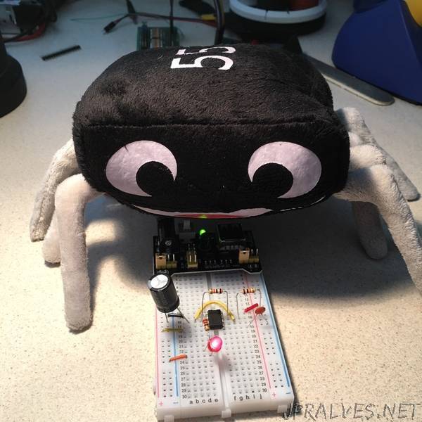
“The 555 was designed back in the early 1970s by Hans Camenzind at the semiconductor company Signetics. It quickly became one of the most popular and used ICs of all time. Data from 2004 shows that it was selling about a billion chips per year and has been used in products ranging from toys to spacecraft.
Background by Dave Astels
There are a few things we will be talking about in our discussion of the 555 that you might not have run into before. To make sure you all have the background, the next few pages will cover some of the basics.
Voltage dividers by Dave Astels
Resistors are inserting components. If you put a voltage across a resistor, a current will flow through it. These three values: voltage, resistance, and current are related by an equation known as “Ohm’s Law”:
V=IR
where
V is the voltage in volts
I is the current in amps
R is the resistance in ohms
This is a very useful equation, mostly because you can manipulate it to help you compute the difference values depending on the situation.
Let’s say you are connecting an LED. You’re using a 5v supply and know you need a currently limiting resistor to keep the LED from frying. An LED will have a specific and well known voltage drop across it. The manufacture’s datasheet will have the specific value, but typically a red LED will have a voltage drop of around 1.8 volts. As the frequency of the emitted light increases, so does the voltage drop so a blue LED might have a voltage drop of closer to 3.3 volts. So if we have a red LED, it will have a 1.8v drop. The other 3.2v has to be across a resistor in series with the LED. What size resistor? If we make the assumption (that’s always worked fine in my experience) that you want 20 milliamps flowing through the LED, then we use
R = V/I
That is, R = 3.2/0.020 = 160”
