
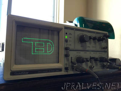
“First, lets go over a few basics. An oscilloscope is a tool for visualizing changing electrical signals. Oscilloscope: Oscillation (changing), scope (viewing). Together they make “oscilloscope”! An oscilloscope works by plotting a voltage over time. That way, you can very easily visualize signals. On older analog scopes, they actually deflect an beam of electrons to make a moving dot on a phosphorescent screen to create a line. But newer digital oscilloscopes still work in pretty much the same way. Oscilloscopes are a very important tool in electronics because they allow engineers and technicians to see the electrical pulses and signals that occur inside electric circuits, even when they occur very rapidly. It is an essential tool for electronics debugging, and is used by anyone who wants to better understand an electrical system. In this instructable, I’ll be showing you how I got mine to display simple vector graphics with only an arduino and some resistors!”