Today we will build a circuit to create a very simple FM transmitter. This circuit like others is well publicized on the Internet and presents a very simple configuration since it only uses an NPN Transistor.
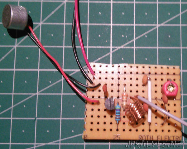
Note that this circuit was assembled on a veroboard because it will not work very well on Breadboard.
The Circuit uses what is called the “Q Factor” of the network that is achieved by the coil and the capacitor to produce a high voltage.
In order for the result to be more effective, it must be ensured that the coil is as close as possible to the capacitor.
To build the reel, use the M6 screw to wind 8 turns around it to form the reel.
To regulate the emission frequency, the variable capacitor must be rotated with a switch that is not metallic (not to affect the emission).
Another NPN transistor can be used.
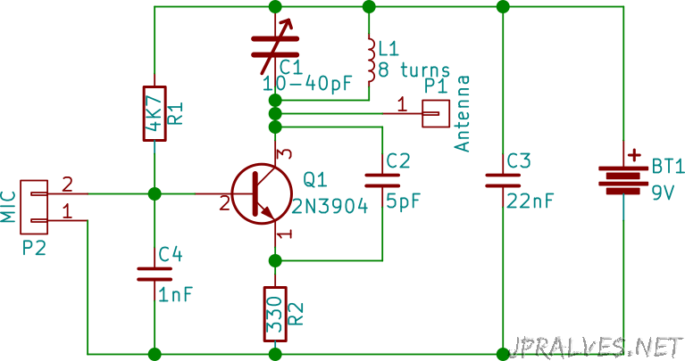
Schematic
Bill of materials (BOM)
Circuit:
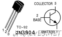
- 1x NPN 2N3904
- 1x Variable Capacitor between 10 and 40nF (C1)
- 1x 5pF Capacitor (C2)
- 1x 22pF Capacitor (C3)
- 1x 1nF Capacitor (C4)
- 1x 4.7K Ohms Resistor (R1)
- 1x 330 Ohms Resistor (R2)
- 1x Inductor (L1)
- 1x MIC
- 1x 9V Battery
IC/Component Pin-out