
“The way to create Low Noise Oscillatror Sinus Wave up 500 MHz, CMOS up 150MHZ, HSTL 1GHz based on DDS from Analog Devices - AD9912
Why did we choose to build a Direct Digital Synthesizer (DDS) based on the AD9912 by Analog Devices?
We opted for the AD9912 because it is a synthesizer with the lowest phase noise available in the market. The manufacturer claims that at a frequency of 100 MHz with a 10 kHz offset, the phase noise is only -145 dBc, and the harmonics are suppressed to -80 dB.
Additionally, the AD9912 features a built-in high-speed comparator, which allows for generating frequencies up to 1 GHz on the differential HSTL output and from a few Hertz up to 150 MHz on the CMOS output.
Furthermore, the AD9912 incorporates two hardware SpurKillers for suppressing selected harmonic levels. However, this topic requires further investigation and experimentation, which we will address at a later stage. The official datasheet from Analog Devices provides more detailed information about this technology.
“The performance improvement offered by this technique varies widely and depends on the conditions used. Given this extreme variability, it is impossible to define a meaningful specification to guarantee SpurKiller performance. Current data indicate that a 6 dB to 8 dB improvement is possible for a given output frequency using a common setting over process, temperature, and voltage. There are frequencies, however, where a common setting can result in much greater improvement. Manually adjusting the SpurKiller settings on individual parts can result in more than 30 dB of spurious performance improvement.”
Analog Devices offers the EVAL-AD9912 Evaluation Board, which is a highly capable board for obtaining the manufacturer’s specifications of the AD9912. However, this board has several significant drawbacks, the main one being its cost: $719 on the mouser.com website. But that’s not the only drawback. To make this board function correctly, it requires seven separate stabilized low-noise power supplies. Furthermore, the board lacks a clock source, so an external clock signal needs to be provided. As a result, using the official Analog Devices board is not as convenient as it may initially appear.
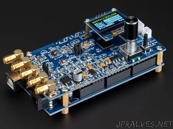
We have set out to create a more affordable and functional board in the form of a shield for the Arduino Mega. Here is a list of the main advantages of our DDS9912 board compared to the board offered by Analog Devices:
- Ready to use out of the box
- Open-source firmware code available on GitHub
- Does not require additional wires and cables
Due to these features, this board is ideal for electronics enthusiasts, hobbyists, as well as laboratories and other researchers in the field of high-frequency RF technology.
To ensure that our frequency synthesizer can work right out of the box, we have installed a total of 8 low-noise LDO (Low Dropout) voltage regulators on the board to provide separate and independent power lines. This allows for the use of a single power supply, preferably 7.5 volts, but it can also be powered via USB. For clocking, we have incorporated a TCXO (Temperature Compensated Crystal Oscillator) on the board, which can be replaced with a 20 or 25 MHz AT Crystal Oscillator if desired, or an external frequency reference can be used.
On the output side, we have included a LPF (Low Pass Filter) to suppress the image harmonic, and an output transformer to suppress even harmonics.
Of course, one could consider using Chinese board options from eBay or Aliexpress based on the AD9912 DDS. However, unfortunately, these boards suffer from several design flaws such as poor PCB routing, inadequate power isolation, which leads to digital noise interfering with the analog section, and the absence of any output filters. All of these issues negate the advantages of the AD9912. Therefore, purchasing such boards is not advisable as it would result in disappointment and wasted money and time.
Let me share the story of how we developed this board. It took us over a year to complete. We took the reference circuit from Analog Devices as the foundation and placed it on a 53mm by 100mm board to match the Arduino Mega shield format. This required us to create a 4-layer PCB. Despite the relatively small size of the board, we managed to accommodate not only the AD9912 itself but also all 8 LDO voltage regulators, an OLED display, an encoder, control buttons, a 9th-order output LPF filter, 2 output transformers, and 5 SMA connectors. Additionally, we included connectors on the board for external buttons and an encoder, in case you want to enclose the device in your own casing. This makes it convenient since you won’t have to solder additional wires to the board.
During the development process, we encountered several interesting problems, which I’ll explain now. The first issue we faced was the heating of the voltage regulators. We addressed this problem by adding resistors that allow for a voltage drop, resulting in less heat generated by the LDO regulators. We also opted for larger package size regulators (DPAK) that can dissipate heat. These measures helped distribute heat more evenly across the board. Another solution to the overheating issue could have been using DC-DC converters, but we had to discard that idea due to the noise they introduce. Initially, we intended to use only 4 power lines, but in this configuration, there were many spurs in the spectrum at offsets of 10 MHz, 1 MHz, and 100 kHz. However, when we followed Analog Devices’ recommendation and separated the power lines, we not only reduced these spurs but also achieved a more even distribution of heat across the board. Unfortunately, we couldn’t completely eliminate these spurs.
Later, we discovered that the main mistake we made was installing 100nF input and output capacitors next to the low-noise voltage regulators LP5709 out of habit. We assumed that this would be sufficient since there was already a 220μF aluminum capacitor nearby. However, according to the LP5709 documentation, it is necessary to install a 1μF ceramic capacitor. After complying with this requirement and replacing all capacitors with 1μF ones, the spurious level dropped by 30-40dB, and in some areas, it decreased below the detection threshold of our devices.
When developing similar devices, it is crucial to be extremely careful in designing PLL loop filter circuits as they are highly sensitive. It is mandatory to install a tantalum capacitor of 10μF and a parallel ceramic capacitor of 100-470nF next to it. This will reduce spurs by 10dB.
The selection of the output transformer deserves special attention as its parameters ensure low harmonics and a uniform frequency response throughout the range. We chose a transformer with a lower limit of 100kHz and an upper limit of 500MHz with a level drop of 3dBm at the range boundaries. Selecting such a transformer will not allow obtaining frequencies below 100kHz, but if needed, this limitation can be easily bypassed by removing the transformer and soldering two resistors and one capacitor in its place (see the instructions).
The AD9912 provides extensive clocking capabilities through hardware implementation. Therefore, we decided to incorporate convenient software support for these features. The main settings are accessible through a graphical menu and adjustable using an encoder. On our board, we install a BALUN to facilitate the transition of clock signals from single-ended to differential, reducing the number of harmonics at the DDS output. Additionally, it allows for quick and easy replacement of the BALUN with a 1GHz HSTL oscillator in a 5x7mm package, such as LP736A00.000000I. Due to the wide variety of clock sources available, we couldn’t rely solely on software control. Therefore, switching between clock sources, in addition to software configuration, also requires hardware configuration, which involves installing one or two capacitors and/or resistors and removing one or two capacitors and/or resistors. When disabling the built-in TCXO, it is recommended to depower it by removing Ferrite Bead FB1. For more details, refer to the corresponding table in the user manual.
In conclusion, I would like to mention that our board’s software is actively being developed (unlike Chinese products that often come without any software). Currently, in addition to the core functionality, we have implemented the Sweep function by means of software, and we plan to incorporate support for the SpureKiller technology mentioned earlier.”