
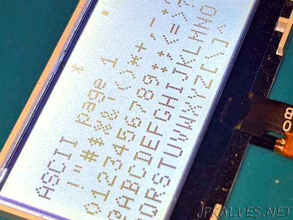
“This is a Noname graphical LCD display salvaged from an unknown device. We are going to figure out its pinout and try to interface it.
Introduction
I am basically writing this tutorial as a note for myself to avoid another reverse engineering session when I happen to use this display again. But I’ll be happy if it would be helpful for you.
Reverse Engineering
So here we have a Noname graphical LCD display without documentation.
It has 12pin 0.5mm connector, and two pins are marked A and K which apparently means anode and cathode of LED backlight. I also noted that A and K tracks were on a separate ribbon that was attached upside down to another 3-12pin ribbon, that is to say, the pinout I was looking for might be partially reversed. If we look closely, it is possible to notice that two traces of the ribbon connector, namely 6 and 7, are definitely wider than others. They are nearly as wide as A and K tracks, therefore I assumed that they were power inputs of the display logic. I guessed that pins 8-9 were SPI interface which takes exactly five pins like on the LCD I reviewed before.”