
“Always I’m interested in how much current is flowing in the electronic circuits I made.
Therefore, I had bought a 1A analog current meter before for measuring the power consumption of circuits.
But the analog meter is forgotten for a quite long time as I don’t know how to use the device to measure current.
But recently I’m beginning to use the INA219 module in several DIY projects and becoming quite comfortable with measuring current with live power supply circuits.
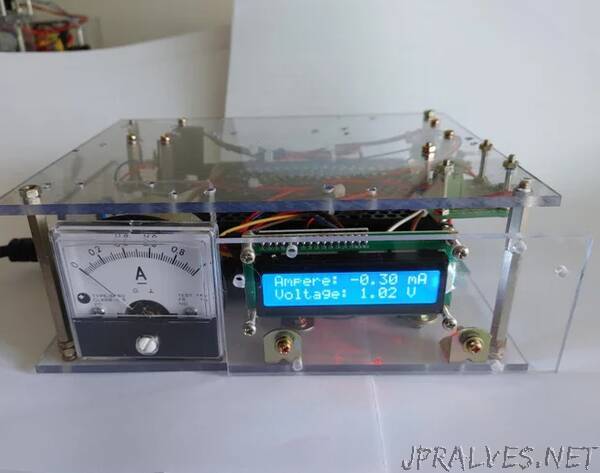
Therefore, I tried to make some useful power supply devices equipped with two different types of current meters as shown in the picture above.
For the DC conversion from 220V AC input and supplying regulated voltage to circuits, a commercially available ready-made switching power supply is used.
The power supply has two channels of 15V power outputs with a maximum 1.5A current supply.
This power supply can be used for energizing any circuits which require regulated DC power.
Also, the power consumption of the circuits can be monitored in terms of the current flow from the power supply to the circuit connected.
Let’s look into more details about this power supply circuit.
Schematics
Basically switching power supply module should be connected to the house 220V wall outlet.
As the electrical wiring method to the house wall outlet is different for every country, please refer to the domestic electricity handling standards of your country.
And please carefully connect three live wires (Neutral, Line, Grounding) to switching power supply input terminals.
As this is a simple power supply circuit, only several components are used for making the final device.
The main goal of this device is to support two channels of power supply outlets equipped with analog and digital current meters.
Only the analog current meter is connected to one side of the 15V power supply channel.
As the analog meter is embedded in an inline style to the output channel, the current drawn from the connected circuit is immediately shown by the needle of the meter.
Meanwhile, the INA219-based digital meter circuit is connected to another 15V channel to show the current flowing into the connected circuit on the LCD.
As the Arduino pro-mini requires an exactly regulated 5V power supply to RAW and GND pins, the LM7805 voltage regulator circuit is used.
Supplies
The most important part of this project is the analog meter.
As the utilization method of the INA219 module is introduced in other Instructables previously posted, I’ll simply explain the digital meter part in the step below,
Anyway, I had bad memories about an analog meter as I got several times of electric shocks while connecting it to audio amplifiers in other DIY projects.
That’s why I’m afraid to use analog meters in my new projects.
But still, I’m curious how much current flow to the circuit I made.
Quit a long time ago (Maybe more than 5 years ago) I bought two analog meters rated as 1A and 2A.
The 1A analog meter is utilized for the power supply circuit which is explained in this story.
The other 2A analog meter is shown in the pictures above.
The usage of an analog meter is not complex as the meter can be simply embedded into hot power wire (Plus polarity terminal) between the power supply and load circuit as shown in the schematics above.
But mounting and fixing the analog meter is difficult as the shape of the meter body is round.
Using acrylic board, “L” shape bracket, and bolts, the analog meter is firmly mounted and fixed on the power supply chassis as shown in the pictures above.
The following parts are used for making this power supply circuit.
- 2 channel 15V switching power supply module (220V input, 2 X 15V 1.5A outputs)
- 220V outlet and 220V rated cables
- 1A analog meter
- Arduino pro-mini (ATmega 328P, 5V, 16MHz)
- INA219 current sensor break out board
- I2C 16x2 LCD module
- LM7805 5V voltage regulator IC, 0,1uF ceramic capacitor, 0.33uF film capacitor
- Acrylic board, metal PCB supporters, universal PCB, bolts and nuts”