
“After running my Arduino controlled Gainclone amp for the last 8 years, the LCD died and I decided that it was time for a revamp. This instructable is based on the original and is designed to be an ‘upgrade’ from that. Please see it here - https://www.instructables.com/Arduino-Powered-Gainclone-amplifier/
This could also be used just as a sound processor/Input switcher board to attach to a commercial AMP but is designed to add some smarts to a generic home made 2 channel amplifier.
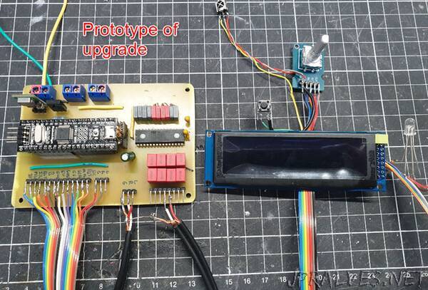
This time around:
- New graphic based OLED screen
- Upgrading to STM32F103 (AKA Bluepill)
- Internal RTC (But with no battery, you could add…)
- Ditching the Radio Module (because I never used it, and it wasn’t implemented well)
- Fixed rotary encoder (It worked but not the best)
- Ability to set the time from controls
- Professionally fabbed board
The STM32F103 is like an Arduino (Nano/Uno etc) on steroids. Although it is magnitudes more powerful than the old Atmega32, the reason I have used it for this upgrade is that it has much more programming space that is needed for storing the fonts for the LCD. The code runs at about 160% of the available space in an Atmega32 chip but only takes 40% of the STM32F103CBT6 or 85% of the STM32F103C8T6 at 55840 bytes.
* This project contains components of dealing with domestic mains voltage and requires knowledge of how to work with it safely. Please ensure your skills match your goals and stay safe. The Author has produced this information with care but takes no responsibility for your actions.***
This also requires some finer soldering skills so please consider this before taking on the project.”