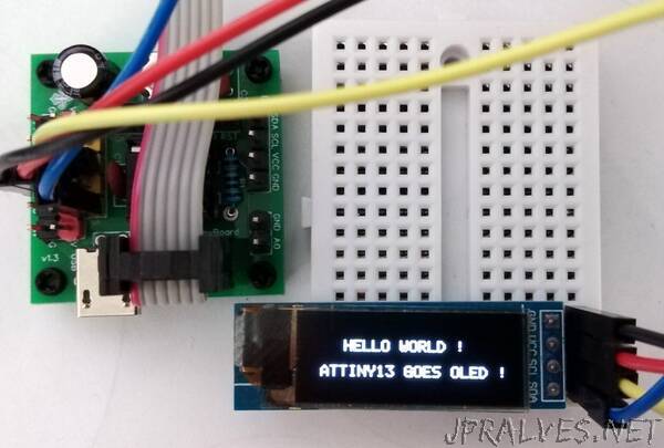
“Connect the OLED module to the ATtiny13A as shown below. The connections for the ATtiny10 are similar. For the ATtiny202 SDA must be connected to PA1 (pin 4) and SCL (or SCK) to PA2 (pin 5).
Since the I²C implementation for ATtiny10/13A is software-based, you can of course use any other I/O pins instead. Just change the relevant definitions in the code. The implementation for the ATtiny202 uses hardware TWI, so the pins provided for this must be used.
I²C Bus, Protocol and Implementation
I²C (Inter-Integrated Circuit) is a serial protocol to connect low-speed devices. It uses only two wires: SCL (serial clock) and SDA (serial data). The I²C bus is a multi master / slave bus. This means that there is at least one I²C master and also at least one I²C slave. The master selects a slave using its slave address, which must be unique within a bus. A data transfer can only be initiated by an I²C master. The slave always remains passive and only listens to the slave address and compares it with its own slave address. Only when it recognizes its slave address does the slave actively intervene in the bus process.”
