
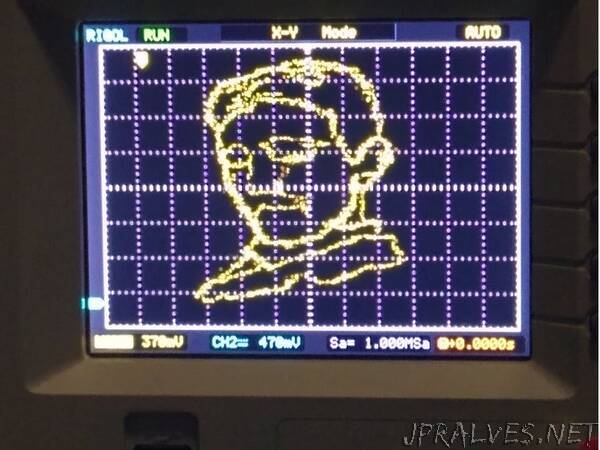
“Ever wanted to display any hand-drawn image on your fancy oscilloscope? Well, now you can!
The R-2R DAC
One of the simplest implementations of a digital to analog converter can be achieved by designing a R-2R ladder DAC. This type of DAC only needs resistors to work making it a very beginner-friendly DAC.
The basic principle of this type of DAC is that you just need two values for resistors. R and 2R. Then you can set them up as shown in the schematic below.
R can be anything as long as each occurrence of R in the schematic is the same value.
For example, if we choose R = 1k, then 2R would just be two times the amount. In this case 2R = 2k. So you could use just 1k and 2k resistors.
If you used R=3.3K then 2R = 6.6k and so on. If you just want to use the same value of resistors for everything, then to get 2R, you would just need to put them two resistors in series and that would increase your component count.
The number of bits are determined by how many branches of 2R you have sticking out. In this project we will be using an 8-bit R-2R and a 6-bit R-2R for the Arduino Uno or Nano. If you are using another microcontroller that you know supports a full port manipulation of at least 8-bits such as the STM32 “blue pill” and “black pill”, then you can just use two 8-bit DACs.
Side remark on DAC ICs:
This project is focused on using a R-2R DAC, but you can feel free to use a DAC IC to achieve something similar. If you’re going to be using a DAC IC, I recommend using one that supports a fast communication protocol such as SPI since I2C will be too slow to draw a detailed image. I will not cover how to use a DAC IC in this post but maybe in a future one. The R-2R still my preferred method as it can output images with more detail.”