
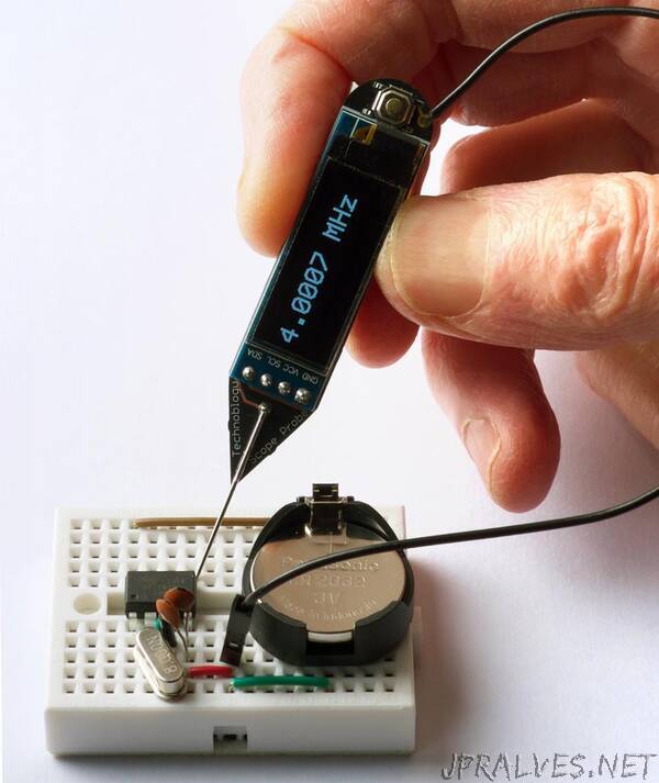
“The Frequency Probe is a handheld tool designed to help you debug your circuits by giving a visual indication of the frequency or voltage at the probe. For a periodic waveform it gives a digital readout of the frequency, with a range of about 1Hz to 5MHz and an accuracy of better than 0.3%. For a voltage level it gives a readout of the voltage:
It is based on an ATtiny84A, and is powered from a small Lipo cell.
Introduction
The obvious way to implement a frequency meter is to count the number of pulses within one second; this then directly gives the frequency. I refer to this as Frequency Mode. The disadvantage of this method is that a long sample time is needed to measure low frequencies accurately.
The other way is to measure the interval between two pulses of the input signal; the reciprocal of this then gives the frequency. I call this Interval Mode. For example, if the interval between pulses is one second the frequency is 1Hz. The disadvantage of this method is that for high frequencies you need to measure the interval very accurately.
The ideal solution is to use Frequency Mode for high frequencies, and Interval Mode for low frequencies, which is the approach I’ve adopted with the Frequency Probe. I explain below how to calculate the best point at which to switch between modes.
I originally started work on this project a couple of years ago, but it turned out to be a lot trickier than I anticipated, and so decided to put it to one side. I revisited it earlier this year, and fortunately managed to solve all the issues.”