
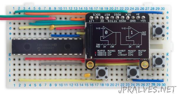
“This is a self-contained tool to allow you to experiment with the configurable op amps provided in the new AVR DB-series processors from Microchip. It shows the configuration as a circuit diagram on the display, and lets you reconfigure it by selecting options from on-screen menus. The display is dynamically updated to reflect the configuration you have selected
It’s based on an Adafruit 240x135 colour TFT display, and an AVR128DB28 microcontroller. This provides two configurable op amps, each of which can be used to amplify low-level signals up to logic levels, or to process the output from the chip’s DAC output. As you press the buttons to change a menu option, the op amp settings are also updated dynamically. So, for example, if you’re using an op amp to amplify an audio signal you’ll hear the volume change as you step between the MUXWIP options, which determine the op amp gain.
In a future article I plan to feature an Op Amp Cookbook, describing a series of projects based on the Pocket Op Amp Lab to demonstrate some interesting applications of the configurable op amps in the AVR DB series.
Introduction
One of the features I really like about the ATtiny85 that I’ve featured in many earlier projects is the programmable gain on the ADC channels, which allows you to create projects that amplify low-level signals like my ATtiny85 Sound Level Meter and Tiny Thermocouple Thermometer. I was therefore very excited when Microchip announced that their DB series include programmable op amps, which allow you to do this and a whole lot more.
Microchip provide an excellent set of tools for configuring the op amps and analysing their performance [1]. However, the idea of having a self-contained op amp laboratory appealed to me, to allow you to interactively configure them and see the results. I’ve learnt a lot by playing around with this project, and I hope you find it interesting too!
How it works
The two op amps in the AVR128DB28 are configured using five register fields. The fields have names such as MUXPOS, where “MUX” means “multiplexer”, another name for an electronic switch, and “POS” identifies the op amp connection being switched, in this case the positive input.
The five register fields are:
- MUXPOS: the op amp’s positive (non-inverting) input.
- MUXNEG: the op amp’s negative (inverting) input.
- MUXBOT: the bottom of the resistor ladder.
- MUXWIP: the resistor ladder wiper position. The resistors always add up to 16R, and this determines the relative values.
- MUXTOP: the top of the resistor ladder.”