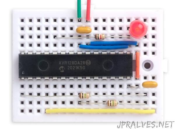
“This article shows how to use the AVR Event System to make buffers or inverters in the DA, DB, DD, EA, or EB series microcontrollers, and gives some practical examples, such as a simple Blink application
Introduction
If you’re designing a project based on an AVR processor and you find you need a few buffers or inverters, one option would be to add a CMOS gate package to your circuit. However, as I found in a recent project, you can often solve the application without any extra components by using the AVR Event System.
The Event System is an under-appreciated aspect of the AVR microcontrollers, probably because it’s a bit unintuitive to use. Although this article only covers simple applications, using buffers or inverters, it should be helpful in understanding how to use the Event System to interconnect other peripherals in the processor.
History
Microchip introduced the Event System as a feature of their new ATtiny 1-series processors, and it has been included in all AVR processors released since then. There have been three iterations of the Event System:
The original version, introduced with the ATtiny 0-series and 1-series, distinguishes between asynchronous channels and synchronous channels.
A second version, introduced with the AVR DA, DB, and DB series processors, simplified the use of channels in events by having just one type of channel; events are synchronous or asynchronous depending on which peripheral is being used. This version of the Event System is also used in the ATtiny 2-series.
A third version, introduced with the AVR EA and EB series processors, extends the second version with more flexibility about which channels you can use with each peripheral.
This tutorial only deals with the second and third versions of the Event System.
How it works
The Event System effectively allows you to configure patch leads inside the microcontroller, going between specified peripheral outputs and peripheral inputs. This article is going to look at the simplest application of this, connecting an I/O input pin to an I/O output pin to make a buffer or inverter.
Terminology
The Event System avoids using the terms “input” or “output” because this could get confusing. For example, the input to the Event System could be the output from a Timer/Counter. It therefore uses the terms “event generator” for the signal initiating the event, and “event user” for the signal that will be changed by the event.
Event generator
In our application the signal coming from the I/O port input is the event generator. You can usually use any I/O port input as an event generator.
There can only be one event generator; it wouldn’t make sense to have more than one input, because there would be a conflict if two inputs had different logic levels.
Event user
In our application the I/O port output that will be changed by the event is the event user. You can have multiple event users for an event.”
